SLIDE 3 ■ Standard measured gas conditions for gas analyzer ■ General Specifications
0 to 50°C
10kPa or lower (The gas outlet should be at atmospheric pressure.)
100μg/Nm3 or lower with particle size of 1μm or lower No mist allowed. Saturated at 2°C (No condensation allowed.) 1ppm or lower Temperature Pressure Dust Mist Moisture
Corrosive component
Measurement principle Measured component Repeatability Linearity Zero drift Span drift
Gas extraction volume
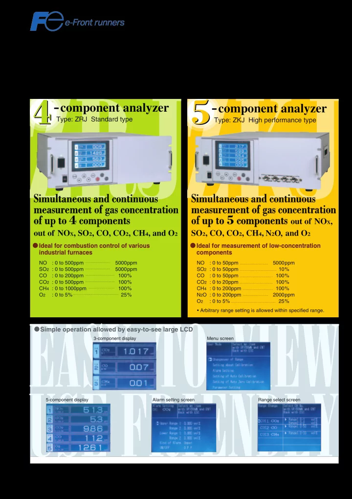
Response time Output signal NOx, SO2, CO, CO2, CH4: Non-dispersive infrared ray system (Double-beam) O2: Paramagnetic type (built in) or zirconia type (Type ZFK7, Separately installed) NO: 0 to 50ppm 5000ppm SO2: 0 to 50ppm 10% CO: 0 to 50ppm 100% CO2: 0 to 20ppm 100% CH4: 0 to 200ppm 100% N2O: 0 to 200ppm 2000ppm O2: 0 to 5% 25% (2-range switching, Maximum range ratio 1:5, O2 excluded) ±0.5%FS (±1%FS for concentration of less than 50ppm) ±1.0%FS or lower ±1.0%FS or lower/week (±2.0%FS/week for concentration from 50ppm to 200ppm) ±2.0%FS or lower/week (±2.0%FS/day for concentration of less than 50ppm) 0.5L/min. ±0.2L/min. 90% response from gas inlet: 60 sec. or shorter 4 to 20mA DC or 0 to 1V DC (Max. non-insulated
Instantaneous output value (measured gas concentration of each component) Instantaneous output value after O2 correction, Average output value after O2 correction, Average O2 output Permissible load resistance: 550Ω or lower (4 to 20mA DC), 100kΩ (0 to 1V DC) External contact input Contact output Communication function Auto calibration function Display
Outside dimension,
weight
Power supply voltage
No voltage contact Auto calibration start, Average value reset, Range selection, Output hold, Pump ON/OFF Range identification of each component, Instrument error, Calibration error, Auto calibration in progress, Pump ON/OFF, CO peak count alarm, Instantaneous value concentration alarm for each component, Power OFF RS-232C (MODBUS) option Auto zero and span calibration (Calibration cycle settable) LCD with backlight Instantaneous value of each component, Instantaneous value after O2 correction, Average value after O2 correction, Average O2 value, CO peak count Parameter setting display (English or Japanese can be selected.) 177 (H) × 483 (W) × 578 (D) mm, About 22kg 100 to 240V AC, 50/60Hz, 250VA
Principle The amount of infrared ray absorbed in
the measurement cell is detected with a mass flow sensor.
Mass flow sensor (Hot-wire wind speed detecting element) Bore: 1mm State of windlessness Detection sensitivity (∆P) When wind is blowing from left Detection sensitivity (∆P) When wind is blowing from right Hot wire temperature
<Mass flow sensor> The low impedance sensor has high noise
- immunity. The sensor with no movable
parts has high resistance to vibration, and thus can be used semipermanently. Infrared ray absorption by measured gas component is converted into electric
- signals. Maximum range ratio of 1:25 is
allowed with the high sensitivity analyzer.
Type: ZKJ
double-beam
Example of gas sampling system configuration
(For measurement of exhaust gas from boilers and refuse incinerators)
■ Zirconia type O2 Sensor
Type : ZFK7
Sample gas outlet Sample cell Interference compensationg detector Sample gas inlet Trimmer Reference cell Mass flow sensor P P-∆P Detector Distribution cell (interference filter) Infrared (single) light source Motor Rotary sector O2 NO,SO2 Gas extractor Gas inlet tube 15°or larger Gas aspirator Mist filter Safety drain trap Gas outlet Drain Electronic gas cooler Flowmeter Membrane filter Membrane filter CO,CO2 (O2) Standard gas ZERO NO SO2 CO2 CO O2 Solenoid valve Pressure reducing valve Infrared gas analyzer ZKJ NO2 /NO converter (for NOx measurement) Zirconia O2 sensor