HL-20 at Mach 6 HL-20 Project Overview HL-20 Project Summary The - - PowerPoint PPT Presentation

hl 20 at mach 6 hl 20 project overview
SMART_READER_LITE
LIVE PREVIEW

HL-20 at Mach 6 HL-20 Project Overview HL-20 Project Summary The - - PowerPoint PPT Presentation

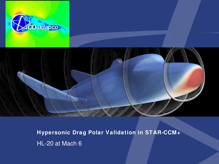
Hypersonic Drag Polar Validation in STAR-CCM+ HL-20 at Mach 6 HL-20 Project Overview HL-20 Project Summary The HL-20 or the Assured Crew Return Vehicle was originally conceived in the late 80s as a lifeboat for those aboard the


slide-1
SLIDE 1

Hypersonic Drag Polar Validation in STAR-CCM+

HL-20 at Mach 6

slide-2
SLIDE 2

HL-20 Project Overview

  • HL-20 Project Summary

The HL-20 or the Assured Crew Return Vehicle was originally conceived in the late ’80s as a lifeboat for those aboard the proposed space station Freedom (and others as time went on). The HL-20 is a blunt- nosed lifting body born out of the lifting body projects in the late ‘60s along with the current Space

  • Shuttle. The primary mission of the HL-20 is to act as a crew re-entry vehicle only and thus has no

payload bays or engines, hence its small size and low cost. Testing began in 1989 to establish an extensive library of coefficient data for future simulation use and put the HL-20 through a full range of Mach numbers, from a full scale model at .05 to a .0197 scale model at mach 20.

  • Project Goal:

Validate STAR-CCM+ for the HL-20 at Mach 6 for AoA -10 to 30

Set the stage and best practices for future work using the real-gas models

  • Outcomes:

Successful Validation of STAR-CCM+ for full angle of attack sweep

Visual validation of oil streaks when compared to similar configuration of the HL-20

  • Future work

Extend Mach range and include Yaw sweeps *Images – Courtesy of NASA

slide-3
SLIDE 3

Validation Source Overview

  • This project was completed using Ware and Cruz’s* paper

presenting results of tests performed at the NASA Langley 20 Mach 6 wind tunnel.

  • Some visual comparisons were made to oil streak images

made in the same tunnel by Horvath et.al.** in their research into the Aerothermodynamic properties of the HL-20

*War are, Geor George M

  • M. and

and Cruz uz, C Chr hristopher I

  • I. Aerodynamic Characteristics
  • f the HL-20. Journal of Spacecraft and Rockets. Vol 30, No. 5,

September-October 1993 **Ho Horvath, T. T.J., J., Rh Rhode, M. N. N., and Buck, ck, G.M Aerothermodynamic Measurements on a Proposed Assured Crew Return Vehicle Lifting Body configuration at Mach 6 and 10. AIAA/ASME 5th Joint Thermophysics and Heat Transfer conference, Seattle WA, June 1990. AIAA-90-1744

slide-4
SLIDE 4

Test Model

  • The Surface used in this study was a laser scan of a one of the HL-20

Test articles.

  • The test article is a .07 scale model of the 24 ft long HL-20
  • Space Dev provided the laser scan files in .STL format

Imported Scan surface (Detail showing surface triangulation)

slide-5
SLIDE 5

STAR-CCM+ Surface Meshing

  • The file was imported into STAR-CCM+ via STL.
  • The first thing to do was split the model on its centerline, in this study the yaw

angle was left fixed at 0.

  • Tessellation of the imported surface was of sufficient detail that it was

determined that the surface needed to be re-meshed to coarsen areas of lower curvature.

Imported surface (full model): 2.2 Million Shells at a constant size of ~.7 mm

Re-meshed surface (half model): 180,000 Shells (excluding free stream boundaries) at a size ranging from .07mm to 6 mm.

slide-6
SLIDE 6

Initial Volume Mesh

  • The polyhedral was chosen in STAR-CCM+ because of the highly complicated shock

structures that develop at high angles of attack.

The polyhedral cell proved to be able capture the shock structures with fewer cells than the hex-based trim mesher.

Finally with such a wide alpha sweep, in excess of 30 degrees, the far field polyhedral cells have a better chance of having flow entering face-normal

Thus the poly cell allowed the full alpha sweep to be performed without a re-gridding

  • peration
  • The Initial grid was made without any knowledge of the flow field so no volume sourcing

was used.

  • Eight prism layers within 1 mm of the wall were used to capture the near wall flow field
slide-7
SLIDE 7

Initial Iso Surface Final Iso Surface

Solution Based Refinement

  • Starting in STAR-CCM+ version 4.02 the user can use ANY closed surface as a

volumetric control

CAD surface

Imported Iso-Surface

  • Iso Surface of mach number to create initial refinement

However this detailed refinement would only be valid for one angle of attack

  • A smoothed and thickened Iso surface was used so that the refinement would account

for all angles of attack.

This was done using the surface repair tools in STAR-CCM+

slide-8
SLIDE 8

Final Volume Mesh

  • 6.4 Million Poly Cells
  • 8 Prism Layers
  • Volumetric Refinement
slide-9
SLIDE 9

Wall Y+

  • The stagnation zone on the nose had a peak Y+ of ~12

while most of the surfaces had Y+<5

slide-10
SLIDE 10

Solution Methods

  • STAR-CCM+ Solver

Coupled Flow

»

2nd-Order Discretization

»

Pre-conditioning

»

Implicit Integration

K-Omega SST Turbulence

Ideal Gas (Real-Gas to be used in Future work)

  • The full alpha sweep and post-processing was done using 20 processors on CD-

adapco’s ‘Orange’ Linux cluster.

  • The runs we run fully batch to sweep the angle of attack and post-process using a

recorded java script

The script will run the configuration to convergence, post-process, and save then increment AOA and repeat

Each configuration was initialized from the previous Alpha

slide-11
SLIDE 11

Convergence Criterion

  • The simulation was given stopping criterion based on deviation of Lift

and Drag

– If both lift and drag did not change more than 5 N in 100 iterations

then the simulation would be judged as converged

» The mean lift and drag values are on the order of 1000-2000 N

  • 2 Simulations were run out to 1500 iterations each to verify the force

based convergence criterion

slide-12
SLIDE 12

Results

slide-13
SLIDE 13

Results

slide-14
SLIDE 14

Results

slide-15
SLIDE 15

Streaklines at AOA 15

slide-16
SLIDE 16

Streaklines at AOA 15

slide-17
SLIDE 17

Streaklines at AOA 15

slide-18
SLIDE 18

Mach Isolines at AOA =30

slide-19
SLIDE 19

Isoline Animations

slide-20
SLIDE 20

Iso Surface Animations