hex modeling protein docking using polar fourier
play

Hex Modeling Protein Docking Using Polar Fourier Correlations The - PowerPoint PPT Presentation

Outline Basic Principles of Docking Fast Fourier Transform (FFT) Docking Methods Hex Polar Fourier Correlation Method Explained Hex Modeling Protein Docking Using Polar Fourier Correlations The CAPRI Experiment Demo: Using Hex on Linux


  1. Outline Basic Principles of Docking Fast Fourier Transform (FFT) Docking Methods Hex Polar Fourier Correlation Method Explained Hex – Modeling Protein Docking Using Polar Fourier Correlations The CAPRI Experiment Demo: Using Hex on Linux Dave Ritchie Team Orpailleur Practical: CAPRI Target 40 – API-A/Trypsin Inria Nancy – Grand Est 2 / 29 Biological Importance of Protein-Protein Interactions 
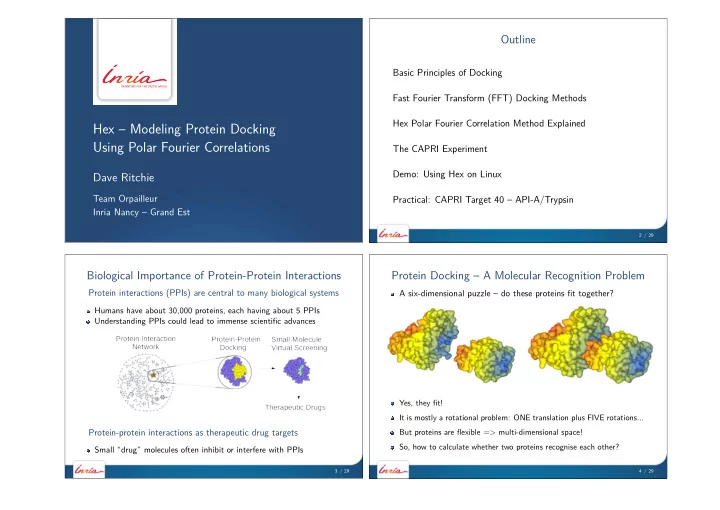
Protein Docking – A Molecular Recognition Problem Protein interactions (PPIs) are central to many biological systems A six-dimensional puzzle – do these proteins fit together? Humans have about 30,000 proteins, each having about 5 PPIs Understanding PPIs could lead to immense scientific advances Yes, they fit! It is mostly a rotational problem: ONE translation plus FIVE rotations... Protein-protein interactions as therapeutic drug targets But proteins are flexible = > multi-dimensional space! So, how to calculate whether two proteins recognise each other? Small “drug” molecules often inhibit or interfere with PPIs 3 / 29 4 / 29

  2. ICM Docking – Multi-Start Pseudo-Brownian Search Protein Docking Using Fast Fourier Transforms Stick pins in protein surfaces at 15˚ A intervals Conventional approaches digitise proteins into 3D Cartesian grids... For each pair of pins, find minimum energy (6 rotations for each): E = E HVW + E CVW + 2 . 16 E el + 2 . 53 E hb + 4 . 35 E hp + 0 . 20 E solv ...and use FFTs to calculated TRANSLATIONAL correlations: � C [∆ x , ∆ y , ∆ z ] = A [ x , y , z ] × B [ x + ∆ x , y + ∆ y , z + ∆ z ] x , y , z BUT for docking, have to repeat for many rotations – expensive! Conventional grid-based FFT docking = SEVERAL CPU-HOURS Often gives good results, but is computationally expensive Katchalski-Katzir et al. (1992) PNAS, 89 2195–2199 Fern´ andez-Recio, Abagyan (2004), J Mol Biol, 335, 843–865 5 / 29 6 / 29 Protein Docking Using Polar Fourier Correlations Some Theory – 2D Spherical Harmonic Surfaces Rigid docking can be considered as a largely ROTATIONAL problem Spherical harmonics (SHs) are classical “special functions” This means we should use ANGULAR coordinate systems z r=(r, θ,φ) θ r y φ x SHs are products of Legendre polynomials and circular functions: Real SHs: y lm ( θ, φ ) = P lm ( θ ) cos m φ + P lm ( θ ) sin m φ Y lm ( θ, φ ) = P lm ( θ ) e im φ Complex SHs: � � Orthogonal: y lm y kj d Ω = Y lm Y kj d Ω = δ lk δ mj j R ( l ) y lm ( θ ′ , φ ′ ) = � With FIVE rotations, we should get a good speed-up? Rotation: jm ( α, β, γ ) y lj ( θ, φ ) 7 / 29 8 / 29

  3. Spherical Harmonic Molecular Surfaces Docking Needs 3D Polar Fourier Representation Use spherical harmonics (SHs) as orthogonal shape “building blocks” Special orthonormal Laguerre-Gaussian radial functions, R nl ( r ) R nl ( r ) = N ( q ) nl e − ρ/ 2 ρ l / 2 L ( l + 1 / 2 ) ρ = r 2 / q , n − l − 1 ( ρ ); q = 20 . Reals SHs y lm ( θ, φ ) , and coeffcients a lm Encode distance from origin as SH series: L l � � r ( θ, φ ) = a lm y lm ( θ, φ ) l = 0 m = − l Calculate coefficients by numerical integration � � 1 ; r ∈ surface skin 1 ; r ∈ protein atom σ ( r ) = τ ( r ) = 0 ; otherwise 0 ; otherwise N n − 1 l � � � a σ Polar Fourier polynomial: σ ( r ) = nlm R nl ( r ) y lm ( θ, φ ) n = 1 l = 0 m = − l Good for shape-matching, not so good for docking... N T ( | m | ) a σ ′ � nl , n ′ l ′ ( R ) a σ Analytic translations: nlm = (1) Ritchie and Kemp (1999), J. Comp. Chem. 20, 383–395 n ′ l ′ m n ′ l ′ 9 / 29 10 / 29 SPF Protein Shape-Density Reconstruction Protein Docking Using SPF Density Functions N � a τ Interior density: τ ( r ) = nlm R nl ( r ) y lm ( θ, φ ) nlm � Image Order Coeffs Favourable: ( σ A ( r A ) τ B ( r B ) + τ A ( r A ) σ B ( r B )) d V A Gaussians - B N = 16 1,496 � Unfavourable: τ A ( r A ) τ B ( r B ) d V C N = 25 5,525 D N = 30 9,455 � Score: S AB = ( σ A τ B + τ A σ B − Q τ A τ B ) d V , Penalty Factor: Q = 11 � � � �� Orthogonality: S AB = a σ nlm b τ nlm + a τ b σ nlm − Qb τ nlm nlm nlm Search: 6D space = 1 distance + 5 Euler rotations: ( R , β A , γ A , α B , β B , γ B ) Ritchie and Kemp (2000), Proteins Struct. Funct. Bionf. 39, 178–194 Ritchie (2003), Proteins Struct. Funct. Bionf. 52, 98–106 11 / 29 12 / 29

  4. Hex SPF Correlation Example – 3D Rotational FFTs Exploiting Proir Knowledge in SPF Docking Set up 3D rotational FFT as a series of matrix multiplications: t = − l R ( l ) ′ nlm = � l Rotate: mt ( 0 , β A , γ A ) a lt a kj T ( | m | ) ′′ nlm = � N ′ Translate: nl , kj ( R ) a a kjm nlt U ( l ) t b nlt U ( l ) ′′ Real to complex: A nlm = � t a tm , B nlm = � tm nl A ∗ nlm B nlv Λ um Multiply: C muv = � lv muv C muv e − i ( m α B + 2 u β B + v γ B ) 3D FFT: S ( α B , β B , γ B ) = � Knowing just one key residue can reduce search space enormously... On one CPU, docking takes from 15 to 30 minute... This accelerates calculation and helps to reduce false-positives... 13 / 29 14 / 29 Docking Very Large Molecules Using Multi-Sampling The CAPRI Experiment Example: docking an antibody to the VP2 viral surface protein CAPRI = “Critical Assessment of PRedicted Interactions” Predictor Software Algorithm T1 T2 T3 T4 T5 T6 T7 Abagyan ICM FF ** *** ** Camacho CHARMM FF * *** *** Eisenstein MolFit FFT * * *** Sternberg FTDOCK FFT * ** * Ten Eyck DOT FFT * * ** Gray MC ** *** Ritchie Hex SPF ** *** Weng ZDOCK FFT ** ** Wolfson BUDDA/PPD GH * *** Bates Guided Docking FF - - - *** Palma BIGGER GF - - ** * Gardiner GAPDOCK GA * * - - - - - Olson Surfdock SH * - - - - Valencia ANN * - - - - - - Vakser GRAMM FFT * - - - - ∗ low, ∗∗ medium, ∗ ∗ ∗ high accuracy prediction; − no prediction Mendez et al. (2003) Proteins Struct. Funct. Bionf. 52, 51–67 15 / 29 16 / 29

  5. Hex Protein Docking Example – CAPRI Target 3 Best Hex Orientation for Target 6 – Amylase/AMD9 Example: best prediction for CAPRI Target 3 – Hemagglutinin/HC63 Ritchie and Kemp (2000), Proteins Struct. Funct. Bionf. 39, 178–194 CAPRI “high accuracy” (Ligand RMSD ≤ 1˚ A) Ritchie (2003), Proteins Struct. Funct. Genet. 52, 98–106 17 / 29 18 / 29 Subsequent CAPRI Targets 8 – 19 CAPRI Results: Targets 8–19 (2003 – 2005) Software T8 T9 T10 T11 T12 T13 T14 T18 T19 ICM ** * ** *** * *** ** ** Target Description Comments PatchDock ** * * * * - ** ** * T8 Nidogen- γ 3 - Laminin U/U ZDOCK/RDOCK ** * *** *** *** ** ** build from monomer – 12˚ FTDOCK * * ** * ** ** * T9 LiCT homodimer A RMS deviation RosettaDock - ** *** ** *** *** build from monomer – 11˚ T10 TBEV trimer A RMS deviation SmoothDock ** *** *** ** ** * T11 Cohesin - dockerin U/U; model-build dockerin RosettaDock *** - - ** *** ** Haddock - - ** ** *** *** T12 Cohesin - dockerin U/B ClusPro ** *** * * SAG1 conformational change: 10˚ T13 SAG1 - antibody Fab A RMS 3D-DOCK ** * * ** * T14 MYPT1 - PP1 δ U/U; model-build PP1 α → PP1 δ MolFit *** * *** ** T18 TAXI - xylanase U/B Hex ** *** * * Zhou - - - *** ** * * T19 Ovine prion - antibody Fab model-build prion DOT *** *** ** ATTRACT ** - - - - *** ** Valencia * * * - - T15-T17 cancelled: solutions were on-line & found by Google !! GRAMM - - - - - ** ** Umeyama ** * Kaznessis - - *** T11, T14, T19 involved homology model-building step... Fano - - * Mendez et al. (2005) Proteins Struct. Funct. Bionf. 60, 150-169 19 / 29 20 / 29

  6. “Hex” and “HexServer” Inside Hex – High Order FFTs, Multi-threading on GPUs Hex: interactive docking ( ∼ 33,000 downloads) – http://hex.loria.fr/ SPF approach = > analytic translational + rotational correlations: js T ( | m | ) � Λ rm js , lv ( R )Λ tm lv e − i ( r β A − s γ A + m α B + t β B + v γ B ) Hexserver ( ∼ 1,000 docking jobs/month) – http://hexserver.loria.fr/ In particular: S AB = jsmlvrt This allows high order FFTs to be used – 1D, 3D, and 5D It also allows calculations to be easily ported to modern GPUs Up to 2048 arithmetic “cores” Up to 8 Gb memory Easy API with C++ syntax Grid of threads model (“SIMT”) Ritchie and Kemp (2000), Proteins 39 178–194 BUT – for best results, need to understand the hardware... ... Ritchie, Kozakov, Vajda (2008), Bioinformatics 24, 1865–1873 Macindoe et al. (2010), Nucleic acids Research, 38, W445–W449 Ritchie and Venkatraman (2010), Bioinformatics, 26, 2398–2405 21 / 29 22 / 29 CUDA Device Architecture CUDA Programming Example – Matrix Multiplication Typically 8–16 multiprocessor blocks, each with 16 thread units Matrix multiplication C = A * B Each thread is responsible for calculating one element: C[i,k] Conventional algorithm: C[i,k] = A[i] * B[k] Thread-block algo uses TILES Tiles of 16x16 is just right! Threads co-operate by reading & sharing tiles of A & B NB. only a very small amount of fast shared memory is available Multi-processor launches multiple blocks to compute all of C NB. global memory is ∼ 80x slower than shared memory Executing thread-blocks concurrently hides global memory latency Strategy: aim for “high arithmetic intensity” in shared memory 23 / 29 24 / 29

Download Presentation
Download Policy: The content available on the website is offered to you 'AS IS' for your personal information and use only. It cannot be commercialized, licensed, or distributed on other websites without prior consent from the author. To download a presentation, simply click this link. If you encounter any difficulties during the download process, it's possible that the publisher has removed the file from their server.

Recommend


More recommend