Hashemite University - - PDF document

hashemite university dr hazim dwairi
SMART_READER_LITE
LIVE PREVIEW

Hashemite University - - PDF document

Hashemite University Dr. Hazim Dwairi Example 7 4: Compatibility Torsion Macgregor and Wight, Fourth Edition in SI units. The one-way joist


slide-1
SLIDE 1

Hashemite University Dr. Hazim Dwairi

1

Example 7‐4: Compatibility Torsion

Macgregor and Wight, Fourth Edition in SI units.

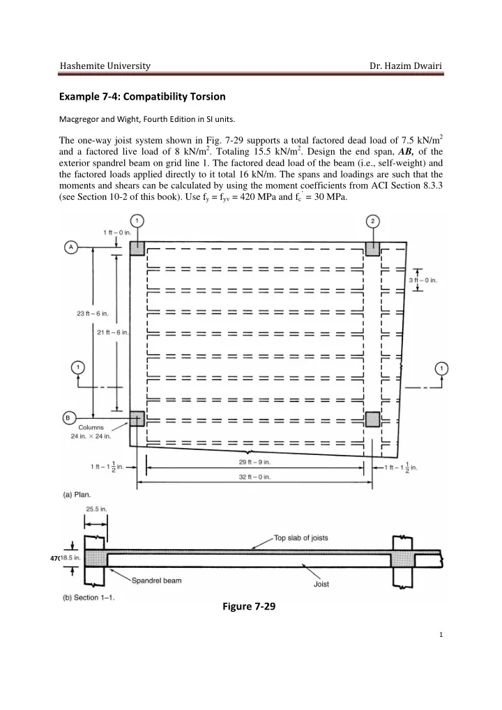
The one-way joist system shown in Fig. 7-29 supports a total factored dead load of 7.5 kN/m2 and a factored live load of 8 kN/m2. Totaling 15.5 kN/m2. Design the end span, AB, of the exterior spandrel beam on grid line 1. The factored dead load of the beam (i.e., self-weight) and the factored loads applied directly to it total 16 kN/m. The spans and loadings are such that the moments and shears can be calculated by using the moment coefficients from ACI Section 8.3.3 (see Section 10-2 of this book). Use fy = fyv = 420 MPa and fc

’ = 30 MPa.

7200 mm 6600 mm 600mm x 600 mm 350 mm 9300 mm 10000 mm 350 mm 900 mm 300 mm 650 mm 470 mm

Figure 7‐29

A B

slide-2
SLIDE 2

Hashemite University Dr. Hazim Dwairi

2

  • 1. Compute the bending moments for the beam. In laying out the floor, it was found that joists

with an overall depth of 470 mm would be required. The slab thickness is 110 mm. The spandrel beam was made the same depth, to save forming costs. The columns supporting the beam are 600 mm square. For simplicity in forming the joists, the beam overhangs the inside face of the columns by 50 mm. Thus, the initial choice of beam size is h = 470 mm, b = 650 mm, and d = 405 mm. Although the joist loads are transferred to the beam by the joist webs, we shall assume a uniform load for simplicity. Very little error is introduced by this assumption. The joist reaction per meter

  • f length of beam is:
  • 2 15.5 9.30

2 72.1 / The total load on the beam is: 72.1 16 88.1 /

The moments in the edge beam are as follows: Exterior end negative:

  • 239.9 .

Midspan positive:

  • 274.1 .

First interior negative:

  • 383.8 .
  • 2. Compute b, d, and h. Since b and h have already been selected, we shall check whether they

are sufficiently large to ensure a ductile flexural behavior. Going through such a check, we find that: . at the first interior negative moment point and that the ratio, , is smaller at

  • ther points. Thus, the section has adequate size for flexure. The areas of steel required for

flexure are as follows: Exterior end negative: As =1791 mm2 Midspan positive: As = 2046 mm2 First interior negative: As = 2865 mm2 Note: The actual steel will be chosen when the longitudinal torsion reinforcement has been calculated.

  • 3. Compute the final M, V, and T, diagrams. The moment and shear diagrams for the edge

beam, computed from the ACI moment coefficients (ACI Section 8.3.3; Section 10-2 of this book): are plotted in Fig. 7-30a and b. The joists are designed as having a clear span of 9300 mm from the face of one beam to the face of the other beam. Because the exterior ends of the joists are "built integrally with" a "spandrel beam." ACI Section 8.3.3 gives the exterior negative moment in the joists as:

slide-3
SLIDE 3

Hashemite University Dr. Hazim Dwairi

3

  • 24

Rather than consider the moments in each individual joist, we shall compute an average moment per meter of width of support: 15.5 9.3 24 55.9 . Although this is a bending moment in the joist, it acts as a twisting moment on the edge beam. As shown in Fig. 7-3la, this moment and the end shear of 72.1 kN/m act at the face of the edge

  • beam. Summing moments about the center of the columns (point A in Fig. 7-31a) gives the

moment transferred to the column as 81.5 kN-m/m. For the design of the edge beam for torsion, we need the torque about the axis of the beam. Summing moments about the centroid of the edge beam (Fig. 7-31b) gives the torque: 81.5 88.1 0.025 79.3 . / OR: 55.9 72.1 0.325 79.3 . / The forces and torque acting on the edge beam per meter of length are shown in Fig. 7-31 b. If the two ends of the beam A-B are fixed against rotation by the columns, the total torque at each end will be: 2 If this is not true, the torque diagram can vary within the range illustrated in Fig. 7-22. For the reasons given earlier, we shall assume that T = tln/2 at each end of member: A-B. This gives the torque diagram shown in Fig. 7-30c. The shear forces in the spandrel beam are: End A:

88.1 6.6/2 290.7

At d from end A:

88.1 . 0.405 255

End B:

1.15 290.7 334.3

At d from end B:

88.1 1.15 . 0.405 298.7

slide-4
SLIDE 4

Hashemite University Dr. Hazim Dwairi

4

Figure 7‐30

+274.1 ‐239.9 ‐383.8 334.3 290.7 255 298.7 30.7 261.7 261.7 55.1 55.1 (kN.m) (kN) (kN.m) (kN.m) (kN.m)

slide-5
SLIDE 5

Hashemite University Dr. Hazim Dwairi

5

Figure 7‐31

650mm 16kN/m 325mm 72.1 kN/m 55.9 kN.m/m 25mm 81.5 kN.m/m 88.1 kN/m 88.1 kN/m 79.3 kN.m/m 79.3 kN.m/m 88.1 kN/m

slide-6
SLIDE 6

Hashemite University Dr. Hazim Dwairi

6

  • 4. Should torsion be considered? If T, exceeds the following. it must be considered:
  • 0.083
  • The effective cross section for torsion is shown in the Fig below. ACI Section 11.6.1 states that

the overhanging flange shall be as defined in ACI Section 13.2.4. The projection of the flange is the smaller of the height of the web below the flange (360 mm) and four times the thickness of the flange (440 mm): 470 650 110 360 345,100

  • 470 650 360 360 110 1010 2960
  • 0.083 0.75 √30 345,100

2960 13,773,327 . 13.8 . Since the maximum torque of 261.7 kN.m exceeds this value, Torsion must be considered.

  • 5. (a) Equilibrium or compatibility torsion? The torque resulting from the 25-mm offset of the

axes of the beam and column (see Fig. 7-31a) is necessary for the equilibrium of the structure and hence is equilibrium torque. The torque at the ends of the beam due to this is: 88.1 0.025 6.2 2 7.3 . On the other hand, the torque resulting from the moments at the ends of the joists exists only because the joint is monolithic and the edge beam has a torsional stiffness. If the torsional stiffness were to decrease to zero: this torque would disappear. This part of the torque is therefore compatibility torsion. Because the loading involves compatibility torsion, we can reduce the maximum torsional moment, Tu, in the spandrel beam, at d from the faces of the columns to:

  • 0.33 0.75 √30 345,100

2960 55.1 . but not less than the equilibrium torque of 7.3 kN-m/m. Assuming the remaining torque after redistribution is evenly distributed along the length of the spandrel beam. The distributed reduced torque, t, due to moments at the ends of the joists has decreased to: 55.1 6.6 2 0.405 9.5 . /

  • 5. (b) Adjust the moments in the joists. The moment diagram for the joists, with the exterior

negative moment of

  • per meter of width of floor, is plotted in Fig. 7-33a. The torsional

moments in the spandrel beam - mainly compatibility moments - can be dissipated by torsional cracking of the spandrel beam. ACI Section 11.6.2.2 allows the negative moment at the joint between the joists and the spandrel beam to be decreased to the value given by (17-31) decreasing from -55.9 kN.m/m to -9.5 kN.m/m, for a reduction of 46.4 kN.m/m in the moment in the one-meter wide strip of joists. This causes a redistribution of the end moment. The

650mm 360mm 110mm 470mm 360mm

slide-7
SLIDE 7

Hashemite University Dr. Hazim Dwairi

7

moment at the spandrel beam end of the joist, end 1, will decrease by 46.4 kN.m/m. Half of this, 23.2 kN.m/m, is carried over to the far end of the joist, as shown in Fig. 7.33b. The changes in the joist end moments at the faces of the spandrel beam and interior beams are +49 kN.m/m and

  • 25.8 kN.m/m. At midspan, the change is +11.6 kN.m/m. The resulting moment diagram per

meter of width is shown in Fig. 7-33c. Each joist supports a 900-mm-wide strip and hence supports 90 percent these moments. The exterior negative-moment steel in the joist should be designed for a negative moment since it is necessary to develop torsional cracks in the spandrel beam before the redistribution can occur. A good rule of thumb is to design the exterior negative steel for the moment computed from

  • , as shown by the dashed line in Fig. 7-33c.

Figure 7‐33

slide-8
SLIDE 8

Hashemite University Dr. Hazim Dwairi

8

  • 6. Is the section big enough for the torsion? For a solid section, the limit on shear and torsion

is given by:

  • 1.7
  • 0.6
  • 470 2 40 12.7650 2 40 12.7 377 557 209,989

2 377 557 1868 298.7 10 650 405

  • 55.1 10 1868

1.7 209,989

  • 0.750.17√30 0.6√30

1.781 3.423 The section is large enough.

  • 7. Compute the stirrup area required for shear in the edge beam. From (ACI Eqs. (11-1) and

(11-2)),

  • 0.17
  • 0.17√30 650 405

1000 240.313

  • At the left end of the beam (End B):
  • 334.3

0.75 240.313 205.42

  • 205.42 10

420 405 1.2076 At d from End B:

  • 298.7

0.75 240.313 157.95

  • 157.95 10

420 405 0.9286 Figure 7-35a illustrates the calculation of

  • . Figure 7-35b is a plot of the As/s required

for shear along the length of the beam. The values of As/s for shear and As/s for torsion (step 8) will be superimposed in step 9.

slide-9
SLIDE 9

Hashemite University Dr. Hazim Dwairi

9

Figure 7‐35

334.3/0.75= 445.7 kN 298.7/0.75= 398.3 kN Vc = 240 kN 340 387.6 240.0 0.866 0.586 1.208 0.929 73.5 18.4 18.4 73.5 0.490 0.123 0.490

  • No. 13 @125mm= 2.064
  • No. 13 @150mm= 1.720

1.566 1.909

  • No. 13 @200mm= 1.290

20@200 mm 1@75 mm + 7@150 mm 1@75 mm + 12@125 mm

slide-10
SLIDE 10

Hashemite University Dr. Hazim Dwairi

10

  • 8. Compute the stirrups required for torsion. From (ACI Eq. (1 1-21)), taking θ = 45o and

Ao= 0.85Aoh gives:

  • 2 0.85
  • 10

2 0.85 209,989 420 6.6697 10

  • 55.1

6.6 2 0.405 9.5 . / At end B, Tu = 62.8 kN.m, Tu/φ= 62.8 kN.m, and At/s= 0.5583 At d from end B, Tu = 55.1 kN.m, Tu/φ = 73.5 kN.m, and At/s= 0.4902 At d from end A, Tu = 55.1 kN.m, Tu/φ = 73.5 kN.m, and At/s= 0.4902 Where Tu is in kN.m and these values are plotted in Fig. 7-35c. At/s is plotted in Fig. 7-35d

  • 9. Add the stirrup areas and select the stirrups.
  • 2
  • At d from End B:
  • 0.9286 2 04902 1.909

For No. 13M double-leg stirrups. s = 135.1 mm Av+t/s is plotted in Fig. 7-35e. The maximum allowable spacings are as follows: for shear (ACI Section 11.5.4.1), d/2 = 202.5 mm; for torsion (ACI Section 11.6.6.1), smaller of 300 mm and ph/s = 1868/8 = 233.5 mm. The dashed horizontal lines in Fig. 7-35e are the values of Av+t/s for No. 13M closed stirrups at spacings of 125 mm (= 2 x 129/125 = 2.064), 150 mm and 200 mm. Stirrups must extend to points where Vu,/φ = Vc/2, or to (d + b), where b, is the width of the portion of the edge beam with closed stirrups, which is 405 + 650 = 1055 mm, past the point where torsional reinforcement is no longer needed, that is, past the points where Tu/φ = (the torque given by (7- 18))/φ = 13.8/0.75 = 18.4 kN-m. These points are indicated in Fig. 7-35c to e. Since they are closer than 1055 mm to midspan, stirrups are required over the entire span. Provide No. 13M closed stirrups: End A: One @ 75 mm, seven @ 150 mm End B: One @ 75 mm, 12 @ 125 mm, then @ 200 mm on centers throughout the rest of the span

slide-11
SLIDE 11

Hashemite University Dr. Hazim Dwairi

11

  • 10. Design the longitudinal reinforcement for torsion.

(a) Longitudinal reinforcement required to resist Tn,

  • where At/s is the amount computed in step 8. This varies along the length of the beam. For

simplicity; we shall keep the longitudinal steel constant along the length of the span and shall base it on the maximum At/s = 0.4902 mm2/mm. Again, 45. We have 0.4902 1868 1 1 916 Alternatively, use (7-30) to compute the required amount of longitudinal reinforcement. Instead

  • f (7-31),
  • 2
  • cot

where Tn = nominal resisting torque. ph = perimeter of closed stirrup = 2(377 + 557) = 1868 mm Ao = area enclosed by centerline of the shear flow path = 0.85Aoh and Aoh is the area inside the centerline of the closed stirrups = 377 x 557 = 209,989 mm2 θ = inclination of cracks. The same valve of θ must be used in (7-30) and (7-31). ACI Section 11.6.3.6 (a) suggests the use of θ = 45o. Substituting in (7-30) gives:

  • 1868

2 0.85 209,989 420 cot45 12.459 10

  • The minimum Al is given by ACI Eq. (11-24):

, 5

  • 12
  • where At/s shall not be less than bw/6fyv = 650/(6 x 420) = 0.2579. Again, At/s varies along the
  • span. The maximum Al will correspond to the minimum At/s. In the center region of the beam,
  • No. 13M stirrups at 200 mm have been chosen. (See Fig. 7-35e.) Assuming half of those stirrups

are for torsion, we shall take At/s = 112 x 2581200 = 0.645 mm2/mm: , 5√30 345,100 12 420 0.645 16861.0 670 Use Al = 916 mm2 From ACI Section 11.6.6.2, the longitudinal steel is distributed around the perimeter of the stirrups with a maximum spacing of 300 mm. There must be a bar in each comer of the stirrups,

slide-12
SLIDE 12

Hashemite University Dr. Hazim Dwairi

12

and these bars have a minimum diameter of 1/24 of the stirrup spacing, but not less than a No. 10

  • bar. The minimum bar diameter corresponds to the maximum stirrup spacing: For 200 mm.

200/24 = 8.33 mm. To satisfy the 300-mm-maximum spacing, we need 3 bars at the top and bottom and one halfway up each side. As per bar = 916/8 = 114.5 mm2. Use No. 16M bars for longitudinal steel Al. The longitudinal torsion steel required at the top of the beam is provided by increasing the area

  • f flexural steel provided at each end and by lap-splicing 3 No. 16M bars with the negative-

moment steel. The lap splices should be at least a Class B tension lap for a No. 16M top bar (see Table 8-4), since all the bars are spliced at the same point. Exterior end negative moment: As = 1791 + 3 x 114.5 = 2134.5 mm2. Use No. 19M bars because bars must be anchored in column. Use 8 No. 19M = 2272 mm2. These fit in one layer. First interior negative moment: As = 2865 + 3 x 114.5 = 3208.5 mm2. Use 7 No. 25M = 3570 mm2. These fit in one layer, minimum width 462 mm. The longitudinal torsional steel required at the bottom is obtained by increasing the area of steel at midspan. The increased area of steel will be extended from support to support. Midspan positive moment: As = 2046 + (3 x 114.5) = 2389.5 mm2 Use 5 No. 25M = 2550 mm2. These fit in one layer. The steel finally chosen is shown in Fig. 7-36. A section through the beam at the first interior support is shown in Fig. 7-34. The cutoff points for the flexural steel were based on Fig. A-5b. except that the area of positive moment steel anchored in the supports by hooks and lap splices was taken equal to the larger of the amounts given in Fig. A-5h and the bottom layer of = 3 x 114.5 = 343.5 mm2. This was rounded up arbitrarily to 2 No. 22M bars.

Figure 7-34

7 No. 25 5 No. 25 x1 = 377mm y1 = 557mm

2 No. 16

  • No. 13 stirrups
slide-13
SLIDE 13

Hashemite University Dr. Hazim Dwairi

13

Figure 7-35

2m 7No25 3No16 1No16 each side 1.5m 8No19 5No25 No13 closed stirrups 20@200mm 1@75mm 12@125mm 1@75mm 7@150mm Hook 2No.22M bars No.13 closed stirrups No.13 closed stirrup Lap Splice 2No.22M bars