
SLIDE 1
Prestressed Concrete Hashemite University
- Dr. Hazim Dwairi
1
The Hashem ite University Departm ent of Civil Engineering
Lecture Lecture 7 7 -
- Design for Shear
Design for Shear
Dr Hazim Dwairi Dr Hazim Dwairi
- Dr. Hazim Dwairi
- Dr. Hazim Dwairi
The Hashemite University The Hashemite University
- Dr. Hazim Dwairi
- Dr. Hazim Dwairi
Shear Stresses Shear Stresses
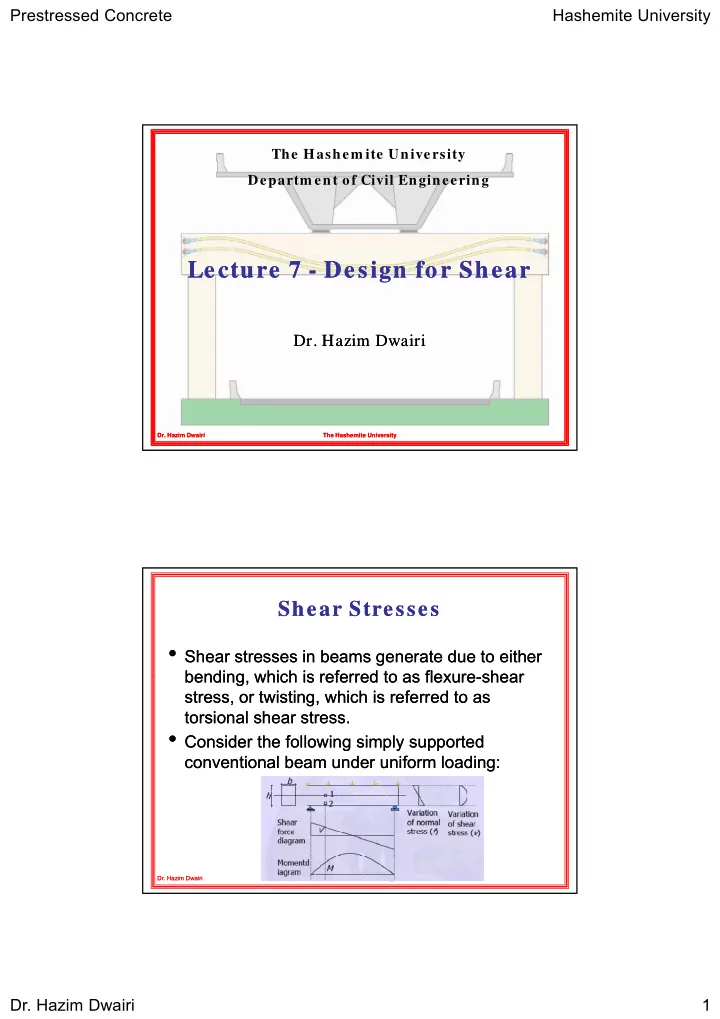
- Shear stresses in beams generate due to either
Shear stresses in beams generate due to either bending which is referred to as flexure bending which is referred to as flexure shear shear bending, which is referred to as flexure bending, which is referred to as flexure-shear shear stress, or twisting, which is referred to as stress, or twisting, which is referred to as torsional shear stress. torsional shear stress.
- Consider the following simply supported
Consider the following simply supported conventional beam under uniform loading: conventional beam under uniform loading:
- Dr. Hazim Dwairi
- Dr. Hazim Dwairi
The Hashemite University The Hashemite University