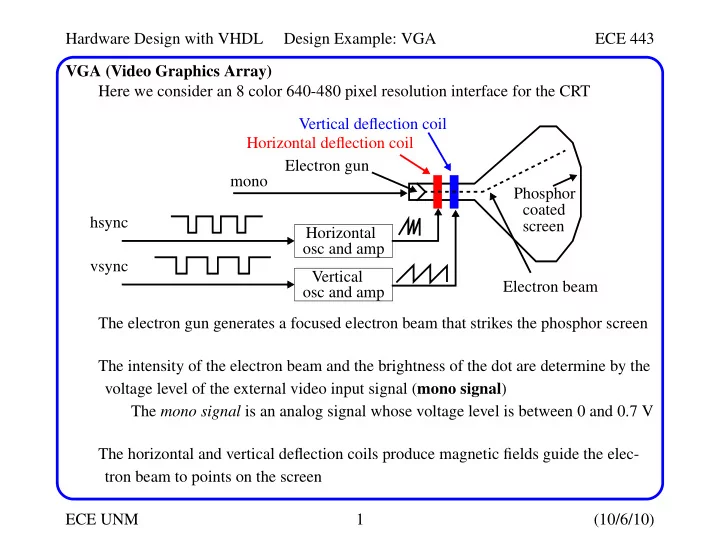
SLIDE 1 Hardware Design with VHDL Design Example: VGA ECE 443 ECE UNM 1 (10/6/10) VGA (Video Graphics Array) Here we consider an 8 color 640-480 pixel resolution interface for the CRT The electron gun generates a focused electron beam that strikes the phosphor screen The intensity of the electron beam and the brightness of the dot are determine by the voltage level of the external video input signal (mono signal) The mono signal is an analog signal whose voltage level is between 0 and 0.7 V The horizontal and vertical deflection coils produce magnetic fields guide the elec- tron beam to points on the screen Electron gun Horizontal
hsync Vertical
vsync Horizontal deflection coil Vertical deflection coil Electron beam Phosphor coated screen mono
SLIDE 2 Hardware Design with VHDL Design Example: VGA ECE 443 ECE UNM 2 (10/6/10) VGA (Video Graphics Array) The electron beam scans the screen systematically in a fixed pattern The horz and vert. osc. and amps gen. sawtooth wfms to control the deflection coils Screen pixel(0,0) h_video_on retrace(96) 639 655 751 799 right border (16) 640 left border (48) ’0’ and ’1’ periods
correspond to rising and falling ramp
hsync
SLIDE 3
Hardware Design with VHDL Design Example: VGA ECE 443 ECE UNM 3 (10/6/10) VGA (Video Graphics Array) A color CRT is similar except that it has three electron beams, that are projected to the red, green and blue phosphor dots on the screen The three dots are combined to form a pixel The three voltage levels determine the intensity of each and therefore the color. The VGA port has five active signals, hsync, vsync, and three video signals for the red, green and blue beams They are connected to a 15-pin D-subminiature connector The video signals are analog signals -- the video controller uses a D-to-A converter to convert the digital output to the appropriate analog level If video is represented by an N-bit word, it can be converted to 2N analog levels. Three video signals can generate 23N different colors (called 3N-bit color) If 1-bit is used for each video signal, we get 23 or 8 colors If all three video signals are driven from the same 1-bit word, we get black&white
SLIDE 4
Hardware Design with VHDL Design Example: VGA ECE 443 ECE UNM 4 (10/6/10) Video Controller For the former case: The video controller generates the sync signals and outputs data pixels serially Red (R) Green (G) Blue (B) Resulting color
black 1 blue
1
green
1
1 cyan
1
red
1
1 magenta
1 1
yellow
1 1
1 white
vga_sync pixel generation circuit hsync vsync external data/control pixel_x pixel_y video_on rgb VGA monitor clk
SLIDE 5
Hardware Design with VHDL Design Example: VGA ECE 443 ECE UNM 5 (10/6/10) Video Controller The vga_sync generates the timing and synchronization signals The hsync and vsync are connected directly to the VGA port These signals drive internal counters that in turn drive pixel_x and pixel_y The video_on signal is used to enable and disable the display pixel_x and pixel_y indicate the relative positions of the scans and essentially specify the location fo the current pixel The pixel generator circuit generates three video signals -- the rgb signal The color value is derived from the external control and data signals The vga_sync circuit generates the hsync signal, which specifies the time to traverse (scan) a row, while the vsync signal specifies the time to traverse the entire screen Assume a 640x480 VGA screen with a 25-MHz pixel rate (known as VGA mode) The screen usually includes a small black border around the visible portion The top-left is coordinate (0, 0) while the bottom right is coordinate (639,479)
SLIDE 6 Hardware Design with VHDL Design Example: VGA ECE 443 ECE UNM 6 (10/6/10) Video Controller One full period of the hsync signal contains 800 pixels and is divided into 4 regions:
- Display: Visible region of screen -- 640 pixels.
- Retrace: Region in which the electron beam returns to left edge. Video signal is
disabled and its length is 96 pixels.
- Right border: Also known as the front porch (porch before retrace). Video signal is
disabled and its length is 16 pixels (may differ depending on monitor).
- Left border: Also known as the back porch. Video signal is disabled and its length
is 48 pixels (may differ depending on monitor). pixel(0,0) retrace(96) 639 655 751 799 right border (16) 640 left border (48) ’0’ and ’1’ periods
correspond to rising and falling ramp
h_video_on hsync
SLIDE 7
Hardware Design with VHDL Design Example: VGA ECE 443 ECE UNM 7 (10/6/10) Video Controller The hsync signal is obtained by a special mod-800 counter and a decoding circuit. The counter starts from the beginning of the display region. This allows the counter’s output to be used as the x-axis coordinate or pixel_x signal. The hsync is low for the counter interval 656 (640+16) to 751 (640+16+96-1). The h_video_on signal is used to ensure that the monitor is black in the border regions and during retrace. It is asserted when the counter is smaller than 640. Vertical synchronization: The time unit of the movement is in terms of the horizontal scan lines. One period of the vsync signal is 525 lines, and has a corresponding set of four regions. retrace(2 lines) 479 489 491 524 bottom border (10 lines) 480 top border (33 lines) v_video_on vsync
SLIDE 8
Hardware Design with VHDL Design Example: VGA ECE 443 ECE UNM 8 (10/6/10) Video Controller A counter is also used here with the output defining the pixel_y coordinate. vsync goes low when line count is 490 or 491. v_video_on is asserted only when line count is less than 480. We assumed the pixel rate was 25 MHz -- this allows 60 screen refreshes/second (anything less results in flicker). s = 60 screens/second * 525 lines/screen * 800 pixels/line = 25.2 Mpixels/sec. HDL Implementation The circuit is implemented with two special counters, a mod-800 counter and a mod-525 counter. The 100 MHz clock is ’divided down’ using an enable tick to enable or pause the counting. This p_tick signal is routed to an output port to coordinate the operation of the pixel generation circuit.
SLIDE 9
Hardware Design with VHDL Design Example: VGA ECE 443 ECE UNM 9 (10/6/10) Video Controller library ieee; use ieee.std_logic_1164.all; use ieee.numeric_std.all; entity vga_sync is port( clk, reset: in std_logic; hsync, vsync, comp_sync: out std_logic; video_on, p_tick: out std_logic; pixel_x, pixel_y: out std_logic_vector(9 downto 0) ); end vga_sync; architecture arch of vga_sync is constant HD: integer:= 640; -- horizontal display constant HF: integer:= 16; -- hsync front porch constant HB: integer:= 48; -- hsync back porch constant HR: integer:= 96; -- hsync retrace
SLIDE 10 Hardware Design with VHDL Design Example: VGA ECE 443 ECE UNM 10 (10/6/10) Video Controller constant VD: integer:= 480; -- vertical display constant VF: integer:= 11; -- vsync front porch constant VB: integer:= 31; -- vsync back porch constant VR: integer:= 2; -- vsync retrace
signal clk_div_reg, clk_div_next: unsigned(1 downto 0);
signal v_cnt_reg, v_cnt_next: unsigned(9 downto 0); signal h_cnt_reg, h_cnt_next: unsigned(9 downto 0);
signal v_sync_reg, h_sync_reg: std_logic; signal v_sync_next, h_sync_next: std_logic; signal h_sync_delay1_reg, h_sync_delay2_reg: std_logic;
SLIDE 11 Hardware Design with VHDL Design Example: VGA ECE 443 ECE UNM 11 (10/6/10) Video Controller signal h_sync_delay1_next, h_sync_delay2_next: std_logic; signal v_sync_delay1_reg, v_sync_delay2_reg: std_logic; signal v_sync_delay1_next, v_sync_delay2_next: std_logic;
signal h_end, v_end, pixel_tick: std_logic; begin
- - ===============================================
process (clk, reset) begin if (reset = ’1’) then clk_div_reg <= to_unsigned(0,2); v_cnt_reg <= (others => ’0’); h_cnt_reg <= (others => ’0’);
SLIDE 12 Hardware Design with VHDL Design Example: VGA ECE 443 ECE UNM 12 (10/6/10) Video Controller v_sync_reg <= ’0’; h_sync_reg <= ’0’; v_sync_delay1_reg <= ’0’; h_sync_delay1_reg <= ’0’; v_sync_delay2_reg <= ’0’; h_sync_delay2_reg <= ’0’; elsif ( clk’event and clk = ’1’ ) then clk_div_reg <= clk_div_next; v_cnt_reg <= v_cnt_next; h_cnt_reg <= h_cnt_next; v_sync_reg <= v_sync_next; h_sync_reg <= h_sync_next;
- - Add to cycles of delay for DAC pipeline.
v_sync_delay1_reg <= v_sync_delay1_next; h_sync_delay1_reg <= h_sync_delay1_next; v_sync_delay2_reg <= v_sync_delay2_next; h_sync_delay2_reg <= h_sync_delay2_next;
SLIDE 13 Hardware Design with VHDL Design Example: VGA ECE 443 ECE UNM 13 (10/6/10) Video Controller end if; end process;
v_sync_delay1_next <= v_sync_reg; h_sync_delay1_next <= h_sync_reg; v_sync_delay2_next <= v_sync_delay1_reg; h_sync_delay2_next <= h_sync_delay1_reg;
- - Generate a 25 MHz enable tick from 100 MHz clock
clk_div_next <= clk_div_reg + 1; pixel_tick <= ’1’ when clk_div_reg = to_unsigned(3,2) else ’0’;
- - h_end and v_end depend on constants above
h_end <= ’1’ when h_cnt_reg=(HD+HF+HB+HR-1) else ’0’; v_end <= ’1’ when v_cnt_reg=(VD+VF+VB+VR-1) else ’0’;
SLIDE 14 Hardware Design with VHDL Design Example: VGA ECE 443 ECE UNM 14 (10/6/10) Video Controller
- - mod-800 horz sync cnter for 640 pixels
- - =======================================
process (h_cnt_reg, h_end, pixel_tick) begin if (pixel_tick = ’1’) then if (h_end = ’1’) then h_cnt_next <= (others => ’0’); else h_cnt_next <= h_cnt_reg + 1; end if; else h_cnt_next <= h_cnt_reg; end if; end process;
SLIDE 15 Hardware Design with VHDL Design Example: VGA ECE 443 ECE UNM 15 (10/6/10) Video Controller
- - mod-525 vertical sync cnter for 480 pixels
- - ===========================================
process (v_cnt_reg, h_end, v_end, pixel_tick) begin if (pixel_tick = ’1’ and h_end = ’1’) then if (v_end = ’1’) then v_cnt_next <= (others => ’0’); else v_cnt_next <= v_cnt_reg + 1; end if; else v_cnt_next <= v_cnt_reg; end if; end process;
SLIDE 16 Hardware Design with VHDL Design Example: VGA ECE 443 ECE UNM 16 (10/6/10) Video Controller
- - horz and vert sync, buffered to avoid glitch
h_sync_next <= ’1’ when (h_cnt_reg >= (HD+HF)) and (h_cnt_reg <= (HD+HF+HR-1)) else ’0’; v_sync_next <= ’1’ when (v_cnt_reg >= (VD+VF)) and (v_cnt_reg <= (VD+VF+VR-1)) else ’0’;
video_on <= ’1’ when (h_cnt_reg < HD) and (v_cnt_reg < VD) else ’0’;
hsync <= h_sync_delay2_reg; vsync <= v_sync_delay2_reg; pixel_x <= std_logic_vector(h_cnt_reg); pixel_y <= std_logic_vector(v_cnt_reg); p_tick <= pixel_tick;
SLIDE 17 Hardware Design with VHDL Design Example: VGA ECE 443 ECE UNM 17 (10/6/10) Video Controller
- - comp sync signal generation
comp_sync <= h_sync_reg xor v_sync_reg; end arch;
SLIDE 18
Hardware Design with VHDL Design Example: VGA ECE 443 ECE UNM 18 (10/6/10) Video Controller TestBench It is easy to test this code by connecting the rgb signal to 3 switches. This will cause the entire screen to change to one of the 8 colors. library ieee; use ieee.std_logic_1164.all; entity vga_test is port( clk, reset: in std_logic; sw: in std_logic_vector(2 downto 0); hsync, vsync, comp_sync: out std_logic; rgb: out std_logic_vector(2 downto 0) ); end vga_test; architecture arch of vga_test is signal rgb_reg: std_logic_vector(2 downto 0); signal video_on: std_logic;
SLIDE 19
Hardware Design with VHDL Design Example: VGA ECE 443 ECE UNM 19 (10/6/10) Video Controller TestBench begin -- instantiate VGA sync circuit vga_sync_unit: entity work.vga_sync port map(clk=>clk, reset=>reset, hsync=>hsync, vsync=>vsync, comp_sync=>comp_sync, video_on=>video_on, p_tick=>open, pixel_x=>open, pixel_y=>open); process(clk, reset) -- rgb buffer begin if (reset = ’1’) then rgb_reg <= (others => ’0’); elsif (clk’event and clk = ’1’) then rgb_reg <= sw; end if; end process; rgb <= rgb_reg when video_on = ’1’ else "000"; end arch;
SLIDE 20 Hardware Design with VHDL Design Example: VGA ECE 443 ECE UNM 20 (10/6/10) Pixel Generation Circuit The pixel generation circuit is responsible for generating the 3-bit rgb signal The external data and control signals define the screen’s content The pixel_x and pixel_y signals from vga_sync define the coordinates There are several ways to deal with content that is displayed
- Bit-mapped scheme
- Time-mapped scheme
- Object-maped scheme
For bit-mapped, a video memory is used to store the data to be displayed Each pixel is mapped directly to a memory word with pixel_x and pixel_y defin- ing the address of the word The graphics processing unit updates the video memory and routes this data to the rgb signal For a 640x480 resolution, this requires about 310 Kbits of display memory for a monochrome display and 930 Kbits for a 3-bit color display
SLIDE 21 Hardware Design with VHDL Design Example: VGA ECE 443 ECE UNM 21 (10/6/10) Pixel Generation Circuit For tile-mapped, display memory is reduced by grouping collection of bits into a tile, that acts as a display unit Define an 8-by-8 square of pixels (64 pixels) as a tile The 640-480 display becomes an 80-by-60 array of tiles, where only 80*60 tiles
- r 4800 words are needed for memory
The number of bits in a word depend on the number of tile patterns, e.g., for 32 tile patterns, word size is 5 bits and display memory is 5*4.8K = 24 Kbits The tile scheme can use ROM to store the tile patterns -- under monochrome using an 8x8 tile pattern requires 64 bits/pattern or 2 Kbits for 32 patterns Total memory then is 24 Kbits + 2 Kbits = 26 Kbits, much smaller than 310 Kbits for bit-mapped A ’text’ display can be implemented this way
SLIDE 22 Hardware Design with VHDL Design Example: VGA ECE 443 ECE UNM 22 (10/6/10) Pixel Generation Circuit For object-mapped, further simplifications are possible where only a few objects are defined Here, most of the screen is blank and is NOT stored explicitly The object generation circuits stores the coordinates of the object and compares them with the current scan location (pixel_x and pixel_y) If the current scan position falls within the object’s region, objx_on is asserted The obj1_rgb indicates the color of the object Object 1 gen. circuit
data/control video_on pixel_x pixel_y rgb mux rgb Object 2 gen. circuit
Object 3 gen. circuit
SLIDE 23
Hardware Design with VHDL Design Example: VGA ECE 443 ECE UNM 23 (10/6/10) Object-Mapped Pixel Generation Circuit The rgb mux performs multiplexing using a priority scheme, i.e., objects with higher priority appear in the foreground Consider a simplified ping-pong game with rectangular objects, a round (ball) object and some animation The rectangular objects can be described by its boundary coordinates on the screen ball paddle wall 639 479 y coordinates x coordinates
SLIDE 24 Hardware Design with VHDL Design Example: VGA ECE 443 ECE UNM 24 (10/6/10) Object-Mapped Pixel Generation Circuit library ieee; use ieee.std_logic_1164.all; use ieee.numeric_std.all; entity pong_graph_st is port( video_on: in std_logic; pixel_x, pixel_y: in std_logic_vector(9 downto 0); graph_rgb: out std_logic_vector(2 downto 0) ); end pong_graph_st; architecture sq_ball_arch of pong_graph_st is
- - x, y coordinates (0,0 to (639, 479)
signal pix_x, pix_y: unsigned(9 downto 0); constant MAX_X: integer := 640; constant MAX_Y: integer := 480;
SLIDE 25 Hardware Design with VHDL Design Example: VGA ECE 443 ECE UNM 25 (10/6/10) Object-Mapped Pixel Generation Circuit
- - wall left and right boundary
constant WALL_X_L: integer := 32; constant WALL_X_R: integer := 35;
- - paddle left, right, top, bottom and height
constant BAR_X_L: integer := 600; constant BAR_X_R: integer := 603; constant BAR_Y_SIZE: integer := 72;
- - top boundary of paddle -- offset from screen middle
constant BAR_Y_T: integer := MAX_Y/2 - BAR_Y_SIZE/2; constant BAR_Y_B: integer := BAR_Y_T + BAR_Y_SIZE - 1;
constant BALL_SIZE: integer := 8; constant BALL_X_L: integer := 580; constant BALL_X_R: integer:= BALL_X_L + BALL_SIZE - 1; constant BALL_Y_T: integer := 238; constant BALL_Y_B: integer:= BALL_Y_T + BALL_SIZE - 1;
SLIDE 26 Hardware Design with VHDL Design Example: VGA ECE 443 ECE UNM 26 (10/6/10) Object-Mapped Pixel Generation Circuit
signal wall_on, bar_on, sq_ball_on: std_logic; signal wall_rgb, bar_rgb, ball_rgb: std_logic_vector(2 downto 0); begin pix_x <= unsigned(pixel_x); pix_y <= unsigned(pixel_y);
- - wall left vertical stripe
wall_on <= ’1’ when (WALL_X_L <= pix_x) and (pix_x <= WALL_X_R) else ’0’; wall_rgb <= "001"; -- blue
bar_on <= ’1’ when (BAR_X_L <= pix_x) and (pix_x <= BAR_X_R) and (BAR_Y_T <= pix_y) and (pix_y <= BAR_Y_B) else ’0’; bar_rgb <= "010"; -- green
SLIDE 27
Hardware Design with VHDL Design Example: VGA ECE 443 ECE UNM 27 (10/6/10) Object-Mapped Pixel Generation Circuit sq_ball_on <= ’1’ when (BALL_X_L <= pix_x) and (pix_x <= BALL_X_R) and (BALL_Y_T <= pix_y) and (pix_y <= BALL_Y_B) else ’0’; ball_rgb <= "100"; -- red process (video_on, wall_on, bar_on, sq_ball_on, wall_rgb, bar_rgb, ball_rgb) begin if (video_on = ’0’) then graph_rgb <= "000"; -- blank else -- priority encoding implicit here if (wall_on = ’1’) then graph_rgb <= wall_rgb; elsif (bar_on = ’1’) then graph_rgb <= bar_rgb; elsif (sq_ball_on = ’1’) then graph_rgb <= ball_rgb;
SLIDE 28
Hardware Design with VHDL Design Example: VGA ECE 443 ECE UNM 28 (10/6/10) Object-Mapped Pixel Generation Circuit else graph_rgb <= "110"; -- yellow bkgnd end if; end if; end process; end sq_ball_arch; The pixel generation circuit above can be combined with the VGA sync code to define a complete interface -- with the following wrapper code. library ieee; use ieee.std_logic_1164.all; entity pong_top_st is port( clk, reset: in std_logic; hsync, vsync, comp_sync: out std_logic; rgb: out std_logic_vector(2 downto 0) ); end pong_top_st;
SLIDE 29 Hardware Design with VHDL Design Example: VGA ECE 443 ECE UNM 29 (10/6/10) Complete VGA Object-Mapped Circuit architecture arch of pong_top_st is signal pixel_x, pixel_y: std_logic_vector(9 downto 0); signal video_on, pixel_tick: std_logic; signal rgb_reg, rgb_next: std_logic_vector(2 downto 0); begin
vga_sync_unit: entity work.vga_sync port map(clk=>clk, reset=>reset, video_on=>video_on, p_tick=>pixel_tick, hsync=>hsync, vsync=>vsync, comp_sync=>comp_sync, pixel_x=>pixel_x, pixel_y=>pixel_y);
SLIDE 30 Hardware Design with VHDL Design Example: VGA ECE 443 ECE UNM 30 (10/6/10) Complete VGA Object-Mapped Circuit
- - instantiate pixel generation circuit
pong_grf_st_unit: entity work.pong_graph_st(sq_ball_arch) port map(video_on=>video_on, pixel_x=>pixel_x, pixel_y=>pixel_y, graph_rgb=>rgb_next);
- - rgb buffer, graph_rgb is routed to the ouput through
- - an output buffer -- loaded when pixel_tick = ’1’.
- - This syncs. rgb output with buffered hsync/vsync sig.
process (clk) begin if (clk’event and clk = ’1’) then if (pixel_tick = ’1’) then rgb_reg <= rgb_next; end if; end if; end process; rgb <= rgb_reg; end arch;
SLIDE 31 Hardware Design with VHDL Design Example: VGA ECE 443 ECE UNM 31 (10/6/10) Displaying Bit Maps For non-rectangular objects, a different approach is needed since it is difficult to check the boundary conditions You can use a bit map to define the object pattern. Let’s make a round ball The process then becomes:
- Check if the scan coordinates are within the 8-by-8 pixel square.
- If so, get the corresponding pixel from the bit map.
- Use the retrieved bit to generate the rgb and on signals
To implement, we need a pattern ROM to store the bit map and an address mapping circuit to convert the scan coordinates to the ROM’s row and column The ROM can be defined using a 2-dimensional constant
SLIDE 32 Hardware Design with VHDL Design Example: VGA ECE 443 ECE UNM 32 (10/6/10) Displaying Bit Maps This code fragment can be substituted into the previous code Note that some of the constants used in previous code are replaced with ’signals’ -- this will allow animation constant BALL_SIZE: integer:= 8;
- - ball left and right boundary
signal ball_x_l, ball_x_r: unsigned(9 downto 0);
- - ball top and bottom boundary
signal ball_y_t, ball_y_b: unsigned(9 downto 0);
type rom_type is array(0 to 7) of std_logic_vector(0 to 7); constant BALL_ROM: rom_type:= ( "00111100", "01111110", "11111111", "11111111", "11111111", "11111111", "01111110", "00111100");
SLIDE 33 Hardware Design with VHDL Design Example: VGA ECE 443 ECE UNM 33 (10/6/10) Displaying Bit Maps signal rom_addr, rom_col: unsigned(2 downto 0); signal rom_data: std_logic_vector(7 downto 0); signal rom_bit: std_logic;
- - new signal to indicate if scan coord is within ball
signal rd_ball_on: std_logic;
- - scan coordinate within square ball.
sq_ball_on <= ’1’ when (ball_x_l <= pix_x) and (pix_x <= ball_x_r) and (ball_y_t <= pix_y) and (pix_y <= ball_y_b) else ’0’;
- - map scan coord to ROM addr/col
rom_addr <= pix_y(2 downto 0) - ball_y_t(2 downto 0); rom_col <= pix_x(2 downto 0) - ball_x_l(2 downto 0); rom_data <= BALL_ROM(to_integer(rom_addr)); rom_bit <= rom_data(to_integer(rom_col)); rd_ball_on <= ’1’ when (sq_ball_on = ’1’) and (rom_bit = ’1’) else ’0’; ball_rgb <= "100";
SLIDE 34
Hardware Design with VHDL Design Example: VGA ECE 443 ECE UNM 34 (10/6/10) Animation Finally, the multiplexing circuit need to be modified to substitute the sq_ball_on sig- nal with the rd_ball_on signal process ... ... elsif (rd_ball_on = ’1’) then graph_rgb <= ball_rgb; ... For animation, the object’s boundaries change gradually to simulate motion This is achieved by using registers to store the boundaries of the object During each scan, the registers are updated In pong, the paddle is controlled by two pushbuttons to move it up and down, while the ball can ’bounce’ in any direction The VGA controller is driven by a 25-MHz pixel rate with a refresh cycle of 60 times per second -- the boundary registers need to be updated at this rate
SLIDE 35 Hardware Design with VHDL Design Example: VGA ECE 443 ECE UNM 35 (10/6/10) Animation We create a 60-Hz enable tick, refr_tick, which is asserted once every 1/60 second To enable motion in the paddle, the constants are replaced with two signals, bar_y_t and bar_y_b (represent the top and bottom boundaries) If a pushbutton is pressed, the bar_y_reg is increased or decreased by a fixed amount (constant BAR_V), but only when the refr_tick is asserted process (bar_y_reg, bar_y_b, bar_y_t, refr_tick, btn) begin bar_y_next <= bar_y_reg; if (refr_tick = ’1’) then
- - if btn 1 pressed and paddle not a bottom yet
if (btn(1) = ’1’ and bar_y_b < (MAX_Y - 1 - BAR_V)) then bar_y_next <= bar_y_reg + BAR_V;
- - if btn 0 pressed and bar not a top yet
elsif (but(0) = ’1’ and bar_y_t > BAR_V) then bar_y_next <= bar_y_reg - BAR_V; end if; ...
SLIDE 36
Hardware Design with VHDL Design Example: VGA ECE 443 ECE UNM 36 (10/6/10) Animation Add animation to the ball is more involved, e.g., we have to replace the 4 boundary constraints with signals and we need two registers The code in the text does not actually implement the game because the ball keeps bouncing whether it hits the paddle or not Working code is given below
SLIDE 37 Hardware Design with VHDL Design Example: VGA ECE 443 ECE UNM 37 (10/6/10) Pong Game Starter library ieee; use ieee.std_logic_1164.all; use ieee.numeric_std.all;
- - btn connected to up/down pushbuttons for now but
- - eventually will get data from UART
entity pong_graph_st is port( clk, reset: in std_logic; btn: in std_logic_vector(1 downto 0); video_on: in std_logic; pixel_x, pixel_y: in std_logic_vector(9 downto 0); graph_rgb: out std_logic_vector(2 downto 0) ); end pong_graph_st;
SLIDE 38 Hardware Design with VHDL Design Example: VGA ECE 443 ECE UNM 38 (10/6/10) Pong Game Starter architecture sq_ball_arch of pong_graph_st is
- - Signal used to control speed of ball and how
- - often pushbuttons are checked for paddle movement.
signal refr_tick: std_logic;
- - x, y coordinates (0,0 to (639, 479)
signal pix_x, pix_y: unsigned(9 downto 0);
constant MAX_X: integer := 640; constant MAX_Y: integer := 480;
- - wall left and right boundary of wall (full height)
constant WALL_X_L: integer := 32; constant WALL_X_R: integer := 35;
SLIDE 39 Hardware Design with VHDL Design Example: VGA ECE 443 ECE UNM 39 (10/6/10) Pong Game Starter
- - paddle left, right, top, bottom and height left &
- - right are constant. top & bottom are signals to
- - allow movement. bar_y_t driven by reg below.
constant BAR_X_L: integer := 600; constant BAR_X_R: integer := 603; signal bar_y_t, bar_y_b: unsigned(9 downto 0); constant BAR_Y_SIZE: integer := 72;
- - reg to track top boundary (x position is fixed)
signal bar_y_reg, bar_y_next: unsigned(9 downto 0);
- - bar moving velocity when a button is pressed
- - the amount the bar is moved.
constant BAR_V: integer:= 4;
- - square ball -- ball left, right, top and bottom
- - all vary. Left and top driven by registers below.
constant BALL_SIZE: integer := 8;
SLIDE 40 Hardware Design with VHDL Design Example: VGA ECE 443 ECE UNM 40 (10/6/10) Pong Game Starter signal ball_x_l, ball_x_r: unsigned(9 downto 0); signal ball_y_t, ball_y_b: unsigned(9 downto 0);
- - reg to track left and top boundary
signal ball_x_reg, ball_x_next: unsigned(9 downto 0); signal ball_y_reg, ball_y_next: unsigned(9 downto 0);
- - reg to track ball speed
signal x_delta_reg, x_delta_next: unsigned(9 downto 0); signal y_delta_reg, y_delta_next: unsigned(9 downto 0);
- - ball movement can be pos or neg
constant BALL_V_P: unsigned(9 downto 0):= to_unsigned(2,10); constant BALL_V_N: unsigned(9 downto 0):= unsigned(to_signed(-2,10));
SLIDE 41 Hardware Design with VHDL Design Example: VGA ECE 443 ECE UNM 41 (10/6/10) Pong Game Starter
type rom_type is array(0 to 7) of std_logic_vector(0 to 7); constant BALL_ROM: rom_type:= ( "00111100", "01111110", "11111111", "11111111", "11111111", "11111111", "01111110", "00111100"); signal rom_addr, rom_col: unsigned(2 downto 0); signal rom_data: std_logic_vector(7 downto 0); signal rom_bit: std_logic;
SLIDE 42 Hardware Design with VHDL Design Example: VGA ECE 443 ECE UNM 42 (10/6/10) Pong Game Starter
- - object output signals -- new signal to indicate if
- - scan coord is within ball
signal wall_on, bar_on, sq_ball_on, rd_ball_on: std_logic; signal wall_rgb, bar_rgb, ball_rgb: std_logic_vector(2 downto 0);
- - ====================================================
begin process (clk, reset) begin if (reset = ’1’) then bar_y_reg <= (others => ’0’); ball_x_reg <= (others => ’0’); ball_y_reg <= (others => ’0’); x_delta_reg <= ("0000000100"); y_delta_reg <= ("0000000100");
SLIDE 43 Hardware Design with VHDL Design Example: VGA ECE 443 ECE UNM 43 (10/6/10) Pong Game Starter elsif (clk’event and clk = ’1’) then bar_y_reg <= bar_y_next; ball_x_reg <= ball_x_next; ball_y_reg <= ball_y_next; x_delta_reg <= x_delta_next; y_delta_reg <= y_delta_next; end if; end process; pix_x <= unsigned(pixel_x); pix_y <= unsigned(pixel_y);
- - refr_tick: 1-clock tick asserted at start of v_sync,
- - e.g., when the screen is refreshed -- speed is 60 Hz
refr_tick <= ’1’ when (pix_y = 481) and (pix_x = 0) else ’0’;
SLIDE 44 Hardware Design with VHDL Design Example: VGA ECE 443 ECE UNM 44 (10/6/10) Pong Game Starter
- - wall left vertical stripe
wall_on <= ’1’ when (WALL_X_L <= pix_x) and (pix_x <= WALL_X_R) else ’0’; wall_rgb <= "001"; -- blue
bar_y_t <= bar_y_reg; bar_y_b <= bar_y_t + BAR_Y_SIZE - 1; bar_on <= ’1’ when (BAR_X_L <= pix_x) and (pix_x <= BAR_X_R) and (bar_y_t <= pix_y) and (pix_y <= bar_y_b) else ’0’; bar_rgb <= "010"; -- green
- - Process bar movement requests
process( bar_y_reg, bar_y_b, bar_y_t, refr_tick, btn) begin bar_y_next <= bar_y_reg; -- no move
SLIDE 45 Hardware Design with VHDL Design Example: VGA ECE 443 ECE UNM 45 (10/6/10) Pong Game Starter if ( refr_tick = ’1’ ) then
- - if btn 1 pressed and paddle not at bottom yet
if ( btn(1) = ’0’ and bar_y_b < (MAX_Y - 1 - BAR_V)) then bar_y_next <= bar_y_reg + BAR_V;
- - if btn 0 pressed and bar not at top yet
elsif ( btn(0) = ’0’ and bar_y_t > BAR_V) then bar_y_next <= bar_y_reg - BAR_V; end if; end if; end process;
- - set coordinates of square ball.
ball_x_l <= ball_x_reg; ball_y_t <= ball_y_reg; ball_x_r <= ball_x_l + BALL_SIZE - 1; ball_y_b <= ball_y_t + BALL_SIZE - 1;
SLIDE 46 Hardware Design with VHDL Design Example: VGA ECE 443 ECE UNM 46 (10/6/10) Pong Game Starter
- - pixel within square ball
sq_ball_on <= ’1’ when (ball_x_l <= pix_x) and (pix_x <= ball_x_r) and (ball_y_t <= pix_y) and (pix_y <= ball_y_b) else ’0’;
- - map scan coord to ROM addr/col -- use low order three
- - bits of pixel and ball positions.
- - ROM row
rom_addr <= pix_y(2 downto 0) - ball_y_t(2 downto 0);
rom_col <= pix_x(2 downto 0) - ball_x_l(2 downto 0);
rom_data <= BALL_ROM(to_integer(rom_addr));
rom_bit <= rom_data(to_integer(rom_col));
- - Turn ball on only if within square and ROM bit is 1.
rd_ball_on <= ’1’ when (sq_ball_on = ’1’) and (rom_bit = ’1’) else ’0’;
SLIDE 47 Hardware Design with VHDL Design Example: VGA ECE 443 ECE UNM 47 (10/6/10) Pong Game Starter ball_rgb <= "100"; -- red
- - Update the ball position 60 times per second.
ball_x_next <= ball_x_reg + x_delta_reg when refr_tick = ’1’ else ball_x_reg; ball_y_next <= ball_y_reg + y_delta_reg when refr_tick = ’1’ else ball_y_reg;
- - Set the value of the next ball position according to
- - the boundaries.
process(x_delta_reg, y_delta_reg, ball_y_t, ball_x_l, ball_x_r, ball_y_t, ball_y_b, bar_y_t, bar_y_b) begin x_delta_next <= x_delta_reg; y_delta_next <= y_delta_reg;
- - ball reached top, make offset positive
if ( ball_y_t < 1 ) then y_delta_next <= BALL_V_P;
SLIDE 48 Hardware Design with VHDL Design Example: VGA ECE 443 ECE UNM 48 (10/6/10) Pong Game Starter
- - reached bottom, make negative
elsif (ball_y_b > (MAX_Y - 1)) then y_delta_next <= BALL_V_N;
- - reach wall, bounce back
elsif (ball_x_l <= WALL_X_R ) then x_delta_next <= BALL_V_P;
- - right corner of ball inside bar
elsif ((BAR_X_L <= ball_x_r) and (ball_x_r <= BAR_X_R)) then
- - some portion of ball hitting paddle, reverse dir
if ((bar_y_t <= ball_y_b) and (ball_y_t <= bar_y_b)) then x_delta_next <= BALL_V_N; end if; end if; end process;
SLIDE 49
Hardware Design with VHDL Design Example: VGA ECE 443 ECE UNM 49 (10/6/10) Pong Game Starter process (video_on, wall_on, bar_on, rd_ball_on, wall_rgb, bar_rgb, ball_rgb) begin if (video_on = ’0’) then graph_rgb <= "000"; -- blank else if (wall_on = ’1’) then graph_rgb <= wall_rgb; elsif (bar_on = ’1’) then graph_rgb <= bar_rgb; elsif (rd_ball_on = ’1’) then graph_rgb <= ball_rgb; else graph_rgb <= "110"; -- yellow bkgnd end if; end if; end process; end sq_ball_arch;
SLIDE 50
Hardware Design with VHDL Design Example: VGA ECE 443 ECE UNM 50 (10/6/10) Pong Game Starter library ieee; use ieee.std_logic_1164.all; entity pong_top_st is port( clk, reset: in std_logic; btn: in std_logic_vector(1 downto 0); hsync, vsync: out std_logic; rgb_8bit: out std_logic_vector(23 downto 0); vga_pixel_tick: out std_logic; blank: out std_logic; comp_sync: out std_logic ); end pong_top_st;
SLIDE 51 Hardware Design with VHDL Design Example: VGA ECE 443 ECE UNM 51 (10/6/10) Pong Game Starter architecture arch of pong_top_st is signal pixel_x, pixel_y: std_logic_vector(9 downto 0); signal video_on: std_logic; signal rgb_reg, rgb_next: std_logic_vector(2 downto 0); signal rgb: std_logic_vector(2 downto 0); signal p_tick: std_logic; begin
vga_sync_unit: entity work.vga_sync port map(clk=>clk, reset=>reset, hsync=>hsync, vsync=>vsync, comp_sync=>comp_sync, video_on=>video_on, p_tick=>p_tick, pixel_x=>pixel_x, pixel_y=>pixel_y);
SLIDE 52 Hardware Design with VHDL Design Example: VGA ECE 443 ECE UNM 52 (10/6/10) Pong Game Starter
- - instantiate pixel generation circuit
pong_grf_st_unit: entity work.pong_graph_st(sq_ball_arch) port map(clk=>clk, reset=>reset, btn=>btn, video_on=>video_on, pixel_x=>pixel_x, pixel_y=>pixel_y, graph_rgb=>rgb_next); vga_pixel_tick <= p_tick;
- - Set the high order bits of the video DAC for each
- - of the three colors
rgb_8bit(7) <= rgb(0); rgb_8bit(15) <= rgb(1); rgb_8bit(23) <= rgb(2);
SLIDE 53 Hardware Design with VHDL Design Example: VGA ECE 443 ECE UNM 53 (10/6/10) Pong Game Starter
- - rgb buffer, graph_rgb is routed to the ouput through
- - an output buffer -- loaded when p_tick = ?1?.
- - This syncs. rgb output with buffered hsync/vsync sig.
process (clk) begin if (clk’event and clk = ’1’) then if (p_tick = ’1’) then rgb_reg <= rgb_next; end if; end if; end process; rgb <= rgb_reg; blank <= video_on; end arch;