Gursharan Singh Tatla 24-Mar-2011 Data Link Protocols Data Link - - PDF document

gursharan singh tatla 24 mar 2011
SMART_READER_LITE
LIVE PREVIEW

Gursharan Singh Tatla 24-Mar-2011 Data Link Protocols Data Link - - PDF document

Gursharan Singh Tatla 24-Mar-2011 Data Link Protocols Data Link Protocols are sets of rule and regulations used to implement data link layer. DATA LINK PROTOCOLS They contain rules for: Line Discipline Flow Control Gursharan


slide-1
SLIDE 1

Gursharan Singh Tatla 24-Mar-2011 www.eazynotes.com 1

Gursharan Singh Tatla

mailme@gursharansingh.in

DATA LINK PROTOCOLS

24-Mar-2011 1 www.eazynotes.com
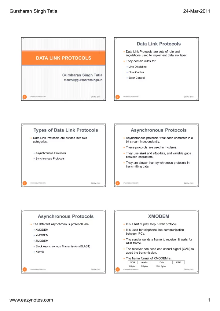
Data Link Protocols

 Data Link Protocols are sets of rule and

regulations used to implement data link layer.

 They contain rules for:  Line Discipline  Flow Control  Error Control

24-Mar-2011 2 www.eazynotes.com

Types of Data Link Protocols

24-Mar-2011 www.eazynotes.com 3

 Data Link Protocols are divided into two

categories:

 Asynchronous Protocols  Synchronous Protocols

Asynchronous Protocols

24-Mar-2011 www.eazynotes.com 4

 Asynchronous protocols treat each character in a

bit stream independently.

 These protocols are used in modems.  They use start and stop bits, and variable gaps

between characters.

 They are slower than synchronous protocols in

transmitting data.

Asynchronous Protocols

24-Mar-2011 www.eazynotes.com 5

 The different asynchronous protocols are:  XMODEM  YMODEM  ZMODEM  Block Asynchronous Transmission (BLAST)  Kermit

XMODEM

24-Mar-2011 www.eazynotes.com 6

 It is a half duplex stop & wait protocol.  It is used for telephone line communication

between PCs.

 The sender sends a frame to receiver & waits for

ACK frame.

 The receiver can send one cancel signal (CAN) to

abort the transmission.

 The frame format of XMODEM is:

SOH Header Data CRC 1 Byte 2 Bytes 128 Bytes

slide-2
SLIDE 2

Gursharan Singh Tatla 24-Mar-2011 www.eazynotes.com 2 XMODEM

24-Mar-2011 www.eazynotes.com 7

 The various fields of frame are:  SOH: It is start of header. It is 1 byte field.  Header: It contains the sequence number. It is 2

bytes in length.

 Data: This field holds 128 bytes of data.  CRC: It is Cyclic Redundancy Check. This field

checks the errors in data field.

YMODEM

24-Mar-2011 www.eazynotes.com 8

 This protocol is similar to XMODEM with the

following major differences:

 Two cancel signals (CAN) are used to abort the

transmission.

 The data field is 1024 bytes long.  ITU-T CRC-16 is used for error checking.

ZMODEM

24-Mar-2011 www.eazynotes.com 9

 It is a combination of XMODEM and YMODEM.

BLAST

24-Mar-2011 www.eazynotes.com 10

 BLAST is more powerful than XMODEM.  It is a full duplex protocol.  It uses sliding window flow control.

Kermit

24-Mar-2011 www.eazynotes.com 11

 It is a terminal program as well as file transfer

protocol.

 It is similar in operation to XMODEM, except that

sender has to wait for a negative acknowledgement (NAK) before it starts transmission.

Synchronous Protocols

24-Mar-2011 www.eazynotes.com 12

 Synchronous Protocols take the whole bit stream

and divide it into characters of equal size.

 These protocols have high speed and are used

for LAN, WAN and MAN.

 Synchronous protocols are categorized into two

groups:

 Character-Oriented Protocol  Bit-Oriented Protocol

slide-3
SLIDE 3

Gursharan Singh Tatla 24-Mar-2011 www.eazynotes.com 3 Character-Oriented Protocol

24-Mar-2011 www.eazynotes.com 13

 It interprets frame as a series of characters.  These are also known as Byte-Oriented

Protocols.

 Control information is inserted as separate control

frames or as addition to existing data frame.

 The example of character-oriented protocol is

Binary Synchronous Communication (BSC) developed by IBM.

Bit-Oriented Protocol

24-Mar-2011 www.eazynotes.com 14

 It interprets frame as a series of bits.  Control information can be inserted as bits

depending on the information to be contained in the frame

 Bit-oriented protocol can pack more information

into shorter frames.

 The examples of bit-oriented protocol are:  Synchronous Data Link Control (SDLC)  High Level Data Link Control (HDLC)

Synchronous Data Link Control (SDLC) Protocol

24-Mar-2011 www.eazynotes.com 15

 SDLC protocol was developed by IBM in 1975.  After developing SDLC, IBM submitted it to

American National Standard Institute (ANSI) and to International Standard Organization (ISO) for acceptance.

 ANSI modified it to ADCCP (Advanced Data

Communication Control Procedure.

 ISO modified it to HDLC (High Level Data Link

Control).

Synchronous Data Link Control (SDLC) Protocol

24-Mar-2011 www.eazynotes.com 16

 The frame format of SDLC is:  The flag sequence of 8-bits 01111110 marks the

beginning and ending of the frame.

 Address field contains the address of the

receiver.

 Control field carries the sequence number,

acknowledgement, requests and responses.

Flag Address Control User Data ECF Flag 8-Bit 8-Bit 16-Bit 01111110 01111110

Synchronous Data Link Control (SDLC) Protocol

24-Mar-2011 www.eazynotes.com 17

 The frame format of SDLC is:  The user data field carries the data and is of

variable length.

 ECF stands for Error Checking Field and is of 16-

  • bits. It is used for error control.

Flag Address Control User Data ECF Flag 8-Bit 8-Bit 16-Bit 01111110 01111110

High Level Data Link Control (HDLC) Protocol

24-Mar-2011 www.eazynotes.com 18

 HDLC came into existence after ISO modified the

SDLC protocol.

 It is a bit-oriented protocol that supports both half

and full duplex communication.

 Systems using HDLC are characterized by:  Station Types  Configuration.  Response Modes

slide-4
SLIDE 4

Gursharan Singh Tatla 24-Mar-2011 www.eazynotes.com 4 Station Types

24-Mar-2011 www.eazynotes.com 19

 To make HDLC protocol applicable to various

network configurations, three types of stations have been defined:

 Primary Station  Secondary Station  Combined Station

Primary Station

24-Mar-2011 www.eazynotes.com 20

 It has complete control over the link at any time.  It has the responsibility of connecting &

disconnecting the link.

 The frames sent by primary station are called

commands.

Secondary Station

24-Mar-2011 www.eazynotes.com 21

 All the secondary stations work under the control

  • f primary station.

 The frames sent by secondary station are called

responses.

Combined Station

24-Mar-2011 www.eazynotes.com 22

 A combined station can behave either as primary

  • r as secondary station.

 It can send commands as well as responses.

Configuration

 Configuration defines how the various stations

are connected to a link.

 There are three possible configurations:  Unbalanced Configuration  Symmetrical Configuration  Balanced Configuration

24-Mar-2011 www.eazynotes.com 23

Unbalanced Configuration

 This type of configuration exists if one station is

primary and other is secondary.

24-Mar-2011 www.eazynotes.com 24

slide-5
SLIDE 5

Gursharan Singh Tatla 24-Mar-2011 www.eazynotes.com 5 Unbalanced Configuration

 It can further be of two types:  Point-to-Point Unbalanced Configuration:

 If there is one primary and one secondary station.

 Multipoint Unbalanced Configuration:

 If there is one primary and many secondary stations.

24-Mar-2011 www.eazynotes.com 25

Symmetrical Configuration

 In this configuration, both sites contain two

stations: one primary and one secondary.

 Primary station of one site is linked with

secondary station of the other and vice versa.

24-Mar-2011 www.eazynotes.com 26

Primary Secondary Primary Secondary

Command Response Command Response Site A Site B

Balanced Configuration

 In this configuration, both sites have combined

stations.

 These combined stations are connected with

single link.

 This single link can be controlled by either station.

24-Mar-2011 www.eazynotes.com 27

Response Modes

 HDLC supports three modes of communication

between stations:

 Normal Response Mode (NRM)  Asynchronous Response Mode (ARM)  Asynchronous Balanced Mode (ABM)

24-Mar-2011 www.eazynotes.com 28

Normal Response Mode (NRM)

 In this mode, primary station controls the link.  Secondary station seeks permission from primary

before transmitting the data.

24-Mar-2011 www.eazynotes.com 29

Asynchronous Response Mode (ARM)

 In this mode, if channel is idle, secondary station

may initiate the transmission without seeking permission from the primary.

 If any secondary station wants to communicate

with other secondary station, the transmission is done via primary station only.

24-Mar-2011 www.eazynotes.com 30

slide-6
SLIDE 6

Gursharan Singh Tatla 24-Mar-2011 www.eazynotes.com 6

Asynchronous Balanced Mode (ABM)

 This type of mode involves combined stations.  There is no primary-secondary relationship, all

stations are equal.

 Therefore, either of the combined station can

initiate the transmission without seeking permission from the other.

24-Mar-2011 www.eazynotes.com 31

Frame Structure in HDLC

 Frame in HDLC can have six fields:  Flag Field: It is the 8-bit field that contains

  • 01111110. It marks the beginning and end of a

frame.

 Address Field: This field contains the address of

the receiver. It is 8-bit long.

24-Mar-2011 www.eazynotes.com 32

Flag Address Control Information FCS Flag

01111110 01111110 8-Bit 8-Bit 8/16-Bit Variable 16-Bit 8-Bit

Frame Structure in HDLC

 Frame in HDLC can have six fields:  Control Field: It carries the sequence number,

acknowledgements, requests and responses. It can be of 8-bit or 16-bit.

 Information Field: It contains user data. Its

length is different for different networks.

24-Mar-2011 www.eazynotes.com 33

Flag Address Control Information FCS Flag

01111110 01111110 8-Bit 8-Bit 8/16-Bit Variable 16-Bit 8-Bit

Frame Structure in HDLC

 Frame in HDLC can have six fields:  FCS Field: FCS stands for Frame Check

  • Sequence. It is the error detection field and is 16-

bit long. It contains either 16-bit CRC or 32-bit CRC.

24-Mar-2011 www.eazynotes.com 34

Flag Address Control Information FCS Flag

01111110 01111110 8-Bit 8-Bit 8/16-Bit Variable 16-Bit 8-Bit

Types of Frames in HDLC

 HDLC defines three types of frames:  Information Frame (I-Frame):

 I-Frames carry user data, and control information about user’s

data.  Supervisory Frame (S-Frame):

 S-Frames carry flow & error control information.

 Unnumbered Frame (U-Frame):

 U-Frames are reserved for system management.  They are used to exchange session management & control

information between the two connected devices.

24-Mar-2011 www.eazynotes.com 35 24-Mar-2011 36 www.eazynotes.com