global register allocation
play

Global Register Allocation Memory Hierarchy Management Register - PowerPoint PPT Presentation

Lecture Outline Global Register Allocation Memory Hierarchy Management Register Allocation via Graph Coloring Register interference graph Graph coloring heuristics Spilling Cache Management Compiler Design I


  1. Lecture Outline Global Register Allocation • Memory Hierarchy Management • Register Allocation via Graph Coloring – Register interference graph – Graph coloring heuristics – Spilling • Cache Management Compiler Design I (2011) 2 
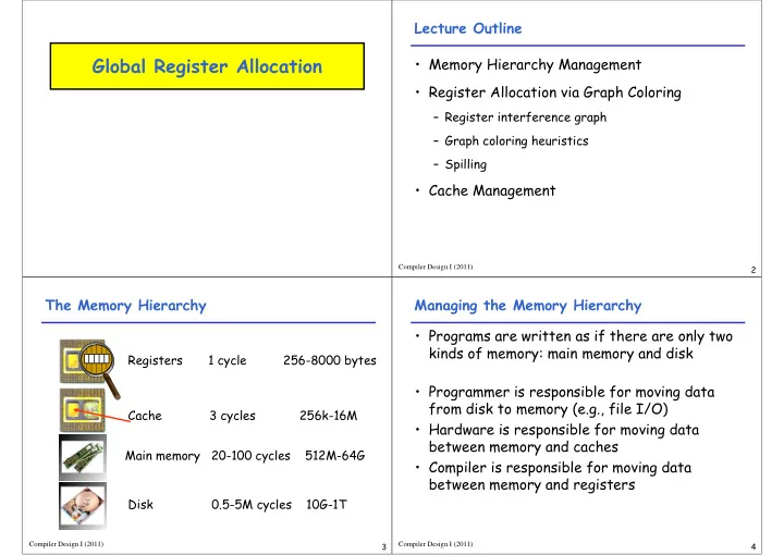
The Memory Hierarchy Managing the Memory Hierarchy • Programs are written as if there are only two kinds of memory: main memory and disk Registers 1 cycle 256-8000 bytes • Programmer is responsible for moving data from disk to memory (e.g., file I/O) Cache 3 cycles 256k-16M • Hardware is responsible for moving data between memory and caches Main memory 20-100 cycles 512M-64G • Compiler is responsible for moving data between memory and registers Disk 0.5-5M cycles 10G-1T Compiler Design I (2011) 3 Compiler Design I (2011) 4

  2. Current Trends The Register Allocation Problem • Power usage limits • Recall that intermediate code uses as many – Size and speed of registers/caches temporaries as necessary – Speed of processors – This complicates final translation to assembly • Improves faster than memory speed (and disk speed) – But simplifies code generation and optimization • The cost of a cache miss is growing – Typical intermediate code uses too many temporaries • The widening gap between processors and memory is bridged with more levels of caches • The register allocation problem: • It is very important to: – Rewrite the intermediate code to use at most as – Manage registers properly many temporaries as there are machine registers – Manage caches properly – Method: Assign multiple temporaries to a register • Compilers are good at managing registers • But without changing the program behavior Compiler Design I (2011) 5 Compiler Design I (2011) 6 History An Example • Consider the program • Register allocation is as old as intermediate code a := c + d e := a + b – Register allocation was used in the original f := e - 1 FORTRAN compiler in the ‘50s with the assumption that a and e die after use – Very crude algorithms • Temporary a can be “reused” after “a + b” • Same with temporary e after “e - 1” • A breakthrough was not achieved until 1980 – Register allocation scheme based on graph coloring • Can allocate a, e, and f all to one register (r 1 ): – Relatively simple, global, and works well in practice r 1 := r 2 + r 3 r 1 := r 1 + r 4 r 1 := r 1 - 1 Compiler Design I (2011) 7 Compiler Design I (2011) 8

  3. Basic Register Allocation Idea Algorithm: Part I • The value in a dead temporary is not needed Compute live variables for each program point: for the rest of the computation – A dead temporary can be reused {b,c,f} a := b + c {a,c,f} d := -a {c,d,f} e := d + f • Basic rule: {c,d,e,f} {c,e} Temporaries t 1 and t 2 can share the same b := d + e {b,c,e,f} register if at all points in the program at f := 2 * e e := e - 1 most one of t 1 or t 2 is live ! {c,f} {c,f} {b,e} b := f + c {b} Compiler Design I (2011) 9 Compiler Design I (2011) 10 The Register Interference Graph Register Interference Graph: Example • Two temporaries that are live simultaneously • For our example: cannot be allocated in the same register a • We construct an undirected graph with b f – A node for each temporary – An edge between t 1 and t 2 if they are live simultaneously at some point in the program c e d • This is the register interference graph (RIG) • E.g., b and c cannot be in the same register – Two temporaries can be allocated to the same register if there is no edge connecting them • E.g., b and d can be in the same register Compiler Design I (2011) 11 Compiler Design I (2011) 12

  4. Register Interference Graph: Properties Graph Coloring: Definitions • It extracts exactly the information needed to • A coloring of a graph is an assignment of characterize legal register assignments colors to nodes, such that nodes connected by an edge have different colors • It gives a global (i.e., over the entire flow graph) picture of the register requirements • A graph is k-colorable if it has a coloring with k colors • After RIG construction, the register allocation algorithm is architecture independent Compiler Design I (2011) 13 Compiler Design I (2011) 14 Register Allocation Through Graph Coloring Graph Coloring: Example • In our problem, colors = registers • Consider the example RIG – We need to assign colors (registers) to graph nodes (temporaries) a r 2 b r 3 r 1 f • Let k = number of machine registers c r 4 r 2 e • If the RIG is k-colorable then there is a register assignment that uses no more than k r 3 d registers • There is no coloring with less than 4 colors • There are various 34-colorings of this graph Compiler Design I (2011) 15 Compiler Design I (2011) 16

  5. Graph Coloring: Example Computing Graph Colorings • Under this coloring the code becomes: • The remaining problem is how to compute a coloring for the interference graph r 2 := r 3 + r 4 • But: r 3 := -r 2 (1) Computationally this problem is NP-hard: r 2 := r 3 + r 1 • No efficient algorithms are known (2) A coloring might not exist for a given number of r 3 := r 3 + r 2 registers r 1 := 2 * r 2 r 2 := r 2 - 1 • The solution to (1) is to use heuristics r 3 := r 1 + r 4 • We will consider the other problem later Compiler Design I (2011) 17 Compiler Design I (2011) 18 Graph Coloring Heuristic Graph Coloring Simplification Heuristic • Observation: • The following works well in practice: – Pick a node t with fewer than k neighbors in RIG – Pick a node t with fewer than k neighbors – Eliminate t and its edges from RIG – Put t on a stack and remove it from the RIG – If the resulting graph has a k-coloring then so does – Repeat until the graph has one node the original graph • Then start assigning colors to nodes on the stack (starting with the last node added) • Why: – At each step pick a color different from those – Let c 1 ,…,c n be the colors assigned to the neighbors assigned to already colored neighbors of t in the reduced graph – Since n < k we can pick some color for t that is different from those of its neighbors Compiler Design I (2011) 19 Compiler Design I (2011) 20

  6. Graph Coloring Example (1) Graph Coloring Example (2) • Start with the RIG and with k = 4: • Start with the RIG and with k = 4: a b b f f Stack: {} Stack: {a} c c e e d d • Remove a • Remove d Compiler Design I (2011) 21 Compiler Design I (2011) 22 Graph Coloring Example (3) Graph Coloring Example (4) • Start assigning colors to: f, e, b, c, d, a • Now all nodes have fewer than 4 neighbors and can be removed: c, b, e, f a r 2 b b r 3 f r 1 f Stack: {d, a} c c r 4 e r 2 e r 3 d Compiler Design I (2011) 23 Compiler Design I (2011) 24

  7. What if the Heuristic Fails? What if the Heuristic Fails? • What if during simplification we get to a state • Remove a and get stuck (as shown below) where all nodes have k or more neighbors ? • Pick a node as a possible candidate for spilling – A spilled temporary “lives” is memory • Example: try to find a 3-coloring of the RIG: – Assume that f is picked as a candidate a b b f f c c e e d d Compiler Design I (2011) 25 Compiler Design I (2011) 26 What if the Heuristic Fails? What if the Heuristic Fails? • Remove f and continue the simplification • On the assignment phase we get to the point when we have to assign a color to f – Simplification now succeeds: b, d, e, c • We hope that among the 4 neighbors of f we used less than 3 colors ⇒ optimistic coloring r 3 b b ? f c c r 1 e r 2 e d d r 3 Compiler Design I (2011) 27 Compiler Design I (2011) 28

  8. Spilling Spilling: Example • Since optimistic coloring failed, we must spill • This is the new code after spilling f temporary f (actual spill) • We must allocate a memory location as the a := b + c d := -a “home” of f f := load fa – Typically this is in the current stack frame e := d + f – Call this address fa b := d + e f := 2 * e • Before each operation that uses f, insert e := e - 1 store f, fa f := load fa • After each operation that defines f, insert f := load fa store f, fa b := f + c Compiler Design I (2011) 29 Compiler Design I (2011) 30 Recomputing Liveness Information Recomputing Liveness Information • The new liveness information after spilling: • New liveness information is almost as before {b,c,f} a := b + c • f is live only {a,c,f} d := -a {c,d,f} – Between a f := load fa and the next instruction f := load fa e := d + f {c,d,e,f} – Between a store f, fa and the preceding instruction {c,d,f} {c,e} b := d + e f := 2 * e {b,c,e,f} {c,f} • Spilling reduces the live range of f e := e - 1 store f, fa {c,f} – And thus reduces its interferences {c,f} f := load fa – Which results in fewer RIG neighbors for f {b,e} b := f + c {c,f} {b} Compiler Design I (2011) 31 Compiler Design I (2011) 32

Download Presentation
Download Policy: The content available on the website is offered to you 'AS IS' for your personal information and use only. It cannot be commercialized, licensed, or distributed on other websites without prior consent from the author. To download a presentation, simply click this link. If you encounter any difficulties during the download process, it's possible that the publisher has removed the file from their server.

Recommend


More recommend