
SLIDE 1
1
- Prof. S. Ben-Yaakov , DC-DC Converters
[4- 1]
Forward and Flyback
(Converters with isolation)
4.1 Transfer of DC current via transformer 4.2 Forward 4.2.1 Voltage transfer function 4.2.2 Magnetization inductance problem 4.2.3 Transformer reset 4.2.4 Reset of forward 4.3 Coupled inductors 4.4 Flyback 4.4.1 Voltage transfer function 4.4.2 Flyback with multiple outputs 4.4.3 Characteristics of Flyback
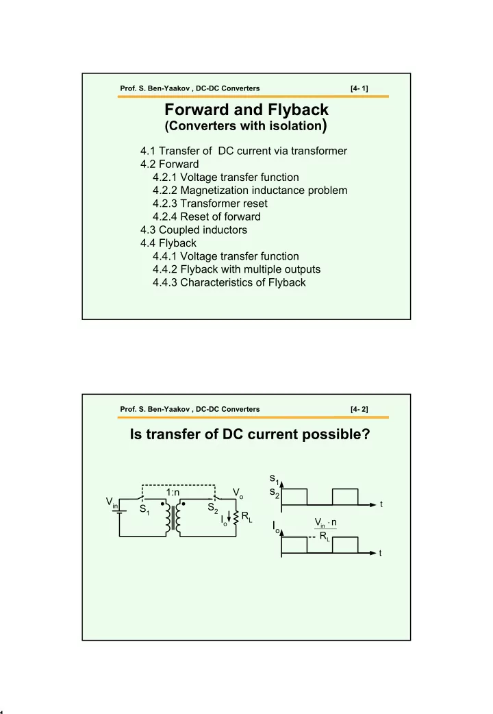
- Prof. S. Ben-Yaakov , DC-DC Converters
[4- 2]
Is transfer of DC current possible?
Io
t
s1
t
L in