
SLIDE 1
1
- Prof. S. Ben-Yaakov , DC-DC Converters
[8- 1]
Drivers
- Prof. S. Ben-Yaakov , DC-DC Converters
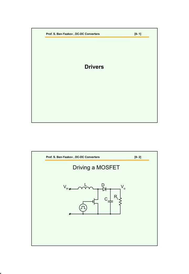
[8- 2]
Drivers Prof. S. Ben-Yaakov , DC-DC Converters [8- 2] Driving a - - PDF document
Prof. S. Ben-Yaakov , DC-DC Converters [8- 1] Drivers Prof. S. Ben-Yaakov , DC-DC Converters [8- 2] Driving a MOSFET L D V in V o R L C 1 Prof. S. Ben-Yaakov , DC-DC Converters [8- 3] Driver Requirements C gd R g I g C ds V s C gs V gs
[8- 1]
[8- 2]
[8- 3]
[8- 4]
[8- 5]
[8- 6]
gd O GS gs GS total
max GS
gs max GS total eq
max gs total eq
[8- 7]
max gs eq
g total
max GS
gs eq
[8- 8]
g total
total g
[8- 9]
[8- 10]
[8- 11]
[8- 12]
[8- 13]
[8- 14]
V2 TD = 0 TF = 0.01u PW = 10u PER = 20u V1 = 0 TR = 0.01u V2 = 15 Dbreak D1
gate L2 {L1*(n*n)} RL {Load} drain V1 {Vin} R4 10meg
C1 220u IC = 6 K K1 COUPLING = 1 K_Linear L1 = l1 L2 = l2 PARAM ET ERS: n = 0.5 Vin = 12 Load = 10 L1 = 300u
+
S1 L1 {L1}
[8- 15]
[8- 16]
n3 n2 n1 Rg
[8- 17]
[8- 18]
[8- 19]
[8- 20]
[8- 21]
[8- 22]
[8- 23]
[8- 24]
[8- 25]
[8- 26]
[8- 27]
[8- 28]
[8- 29]