Fluid Mechanics 9-1a1 Definitions Fluids Substances in either - - PowerPoint PPT Presentation

fluid mechanics 9 1a1
SMART_READER_LITE
LIVE PREVIEW

Fluid Mechanics 9-1a1 Definitions Fluids Substances in either - - PowerPoint PPT Presentation

Fluid Mechanics 9-1a1 Definitions Fluids Substances in either the liquid or gas phase Cannot support shear Density Mass per unit volume Specific Volume Specific Weight g m = g = lim V


slide-1
SLIDE 1

Professional Publications, Inc.

FERC

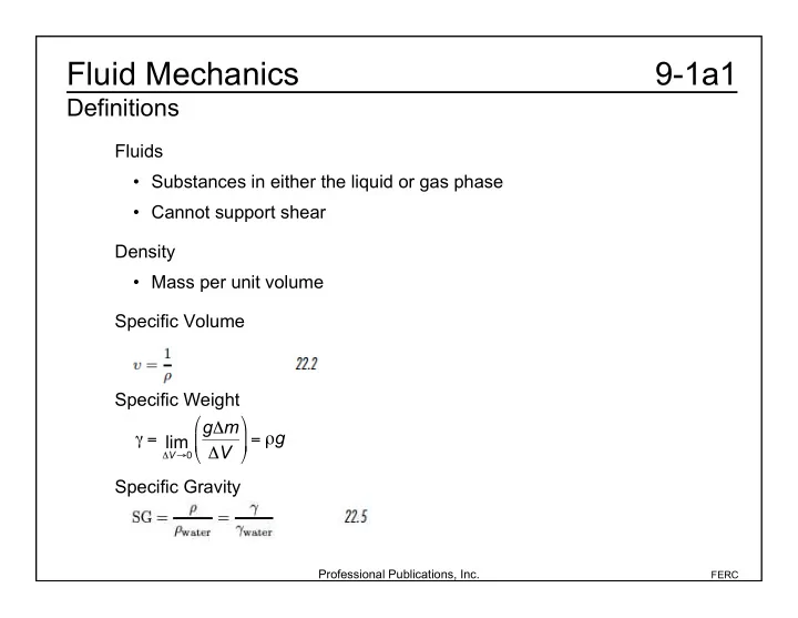
9-1a1 Fluid Mechanics

Definitions

Fluids

  • Substances in either the liquid or gas phase
  • Cannot support shear

Density

  • Mass per unit volume

Specific Volume Specific Weight Specific Gravity =

V0

lim gm V

  • = g
slide-2
SLIDE 2

Professional Publications, Inc.

FERC

9-1a2 Fluid Mechanics

Definitions

Example (FEIM): Determine the specific gravity of carbon dioxide gas (molecular weight = 44) at 66°C and 138 kPa compared to STP air. Rcarbon dioxide = 8314 J kmolK 44 kg kmol = 189 J/kgK Rair = 8314 J kmolK 29 kg kmol = 287 J/kgK SG =

  • STP

= PRairTSTP RCO 2TpSTP = 1.3810

5 Pa

189 J kgK

  • (66°C+ 273.16)
  • 287

J kgK

  • (273.16)

1.01310

5 Pa

  • = 1.67
slide-3
SLIDE 3

Professional Publications, Inc.

FERC

9-1b Fluid Mechanics

Definitions

Shear Stress

  • Normal Component:
  • Tangential Component
  • For a Newtonian fluid:
  • For a pseudoplastic or dilatant fluid:
slide-4
SLIDE 4

Professional Publications, Inc.

FERC

9-1c1 Fluid Mechanics

Definitions

Absolute Viscosity

  • Ratio of shear stress to rate of shear deformation

Surface Tension Capillary Rise

slide-5
SLIDE 5

Professional Publications, Inc.

FERC

9-1c2 Fluid Mechanics

Definitions

Example (FEIM): Find the height to which ethyl alcohol will rise in a glass capillary tube 0.127 mm in diameter. Density is 790 kg/m

3, = 0.0227 N/m, and = 0°.

h = 4 cos d = (4) 0.0227 kg s

2

  • (1.0)

790 kg m

3

  • 9.8 m

s

2

  • (0.12710

3m)

= 0.00923 m

slide-6
SLIDE 6

Professional Publications, Inc.

FERC

9-2a1 Fluid Mechanics

Fluid Statics

Gage and Absolute Pressure Hydrostatic Pressure pabsolute = pgage + patmospheric p = h +gh p2 p1 = (z2 z1) (A) ethyl alcohol (B) oil (C) water (D) glyceri Example (FEIM): In which fluid is 700 kPa first achieved?

slide-7
SLIDE 7

Professional Publications, Inc.

FERC

9-2a2 Fluid Mechanics

Fluid Statics

Therefore, (D) is correct. p0 = 90 kPa p1 = p0 + 1h1 = 90 kPa + 7.586kPa m

  • (60 m) = 545.16 kPa

p2 = p1 + 2h2 = 545.16 kPa + 8.825kPa m

  • (10 m) = 633.41 kPa

p3 = p2 + 3h3 = 633.41 kPa + 9.604kPa m

  • (5 m) = 681.43 kPa

p4 = p3 + 4h4 = 681.43 kPa + 12.125 kPa m

  • (5 m) = 742 kPa
slide-8
SLIDE 8

Professional Publications, Inc.

FERC

9-2b1 Fluid Mechanics

Fluid Statics

Manometers

slide-9
SLIDE 9

Professional Publications, Inc.

FERC

9-2b2 Fluid Mechanics

Fluid Statics

From the table in the NCEES Handbook, mercury = 13560 kg m

3 water = 997 kg/m 3

Example (FEIM): The pressure at the bottom of a tank of water is measured with a mercury

  • manometer. The height of the water is 3.0 m and the height of the mercury is

0.43 m. What is the gage pressure at the bottom of the tank? p = g 2h2 1h1

( )

= 9.81m s

2

  • 13560 kg

m

3

  • (0.43 m) 997 kg

m

3

  • (3.0 m)
  • = 27858 Pa
slide-10
SLIDE 10

Professional Publications, Inc.

FERC

9-2c Fluid Mechanics

Fluid Statics

Barometer Atmospheric Pressure

slide-11
SLIDE 11

Professional Publications, Inc.

FERC

9-2d Fluid Mechanics

Fluid Statics

Forces on Submerged Surfaces Example (FEIM): The tank shown is filled with water. Find the force on 1 m width of the inclined portion. The average pressure on the inclined section is: The resultant force is pave =

1 2

( ) 997 kg

m

3

  • 9.81m

s

2

  • 3 m+5 m

( )

= 39122 Pa R = paveA = 39122 Pa

( ) 2.31 m ( ) 1 m ( )

= 90372 N

slide-12
SLIDE 12

Professional Publications, Inc.

FERC

9-2e Fluid Mechanics

Fluid Statics

Center of Pressure If the surface is open to the atmosphere, then p0 = 0 and

slide-13
SLIDE 13

Professional Publications, Inc.

FERC

9-2f1 Fluid Mechanics

Fluid Statics

Example 1 (FEIM): The tank shown is filled with water. At what depth does the resultant force act? The surface under pressure is a rectangle 1 m at the base and 2.31 m tall. A = bh Iyc = b

3h

12 Zc = 4 m sin60° = 4.618 m

slide-14
SLIDE 14

Professional Publications, Inc.

FERC

9-2f2 Fluid Mechanics

Fluid Statics

Rdepth = (Zc + z*) sin 60° = (4.618 m + 0.0963 m) sin 60° = 4.08 m z* = Iyc AZc = b

3h

12bhZc = b

2

12Zc = (2.31 m)

2

(12)(4.618 m) = 0.0963 m Using the moment of inertia for a rectangle given in the NCEES Handbook,

slide-15
SLIDE 15

Professional Publications, Inc.

FERC

9-2g Fluid Mechanics

Fluid Statics

Example 2 (FEIM): The rectangular gate shown is 3 m high and has a frictionless hinge at the bottom. The fluid has a density of 1600 kg/m3. The magnitude of the force F per meter of width to keep the gate closed is most nearly R is one-third from the bottom (centroid

  • f a triangle from the NCEES Handbook).

Taking the moments about R, 2F = Fh Therefore, (B) is correct. pave = gzave(1600 kg m

3)(9.81m

s

2)(1 2)(3 m)

= 23544 Pa R w = paveh = (23544 Pa)(3 m) = 70662 N/m F +F

h = R

F w = 1 3

  • R

w

  • =

70,667 N m 3 = 23.6 kN/m (A) 0 kN/m (B) 24 kN/m (C) 71 kN/m (D) 370 kN/m

slide-16
SLIDE 16

Professional Publications, Inc.

FERC

9-2h Fluid Mechanics

Fluid Statics

Archimedes’ Principle and Buoyancy

  • The buoyant force on a submerged or floating object is equal to the

weight of the displaced fluid.

  • A body floating at the interface between two fluids will have buoyant

force equal to the weights of both fluids displaced. F

buoyant = waterVdisplaced

slide-17
SLIDE 17

Professional Publications, Inc.

FERC

9-3a Fluid Mechanics

Fluid Dynamics

Hydraulic Radius for Pipes r = 3 m d = 2 m = (2 m)(arccos((r d)/ r)) = (2 m)(arccos 1

3) = 2.46 radians

Example (FEIM): A pipe has diameter of 6 m and carries water to a depth of 2 m. What is the hydraulic radius? (Careful! Degrees are very wrong here.) s = r = (3 m)(2.46 radians) = 7.38 m A = 1

2 (r 2( sin)) = (1 2)((3 m) 2(2.46 radians sin2.46)) = 8.235 m 2

RH = A s = 8.235 m

2

7.38 m = 1.12 m

slide-18
SLIDE 18

Professional Publications, Inc.

FERC

9-3b Fluid Mechanics

Fluid Dynamics

Continuity Equation If the fluid is incompressible, then 1 = 2.

slide-19
SLIDE 19

Professional Publications, Inc.

FERC

9-3c Fluid Mechanics

Fluid Dynamics

Example (FEIM): The speed of an incompressible fluid is 4 m/s entering the 260 mm pipe. The speed in the 130 mm pipe is most nearly (A) 1 m/s (B) 2 m/s (C) 4 m/s (D) 16 m/s Therefore, (D) is correct. A

1v1 = A2v2

A

1 = 4A2

so v2 = 4v1 = 4

( ) 4m

s

  • = 16 m/s
slide-20
SLIDE 20

Professional Publications, Inc.

FERC

9-3d1 Fluid Mechanics

Fluid Dynamics

Bernoulli Equation

  • In the form of energy per unit mass:

p1 1 + v1

2

2 + gz1 = p2 2 + v2

2

2 + gz2

slide-21
SLIDE 21

Professional Publications, Inc.

FERC

9-3d2 Fluid Mechanics

Fluid Dynamics

Example (FEIM): A pipe draws water from a reservoir and discharges it freely 30 m below the surface. The flow is frictionless. What is the total specific energy at an elevation of 15 m below the surface? What is the velocity at the discharge?

slide-22
SLIDE 22

Professional Publications, Inc.

FERC

9-3d3 Fluid Mechanics

Fluid Dynamics

Let the discharge level be defined as z = 0, so the energy is entirely potential energy at the surface. Esurface = zsurface g = (30 m) 9.81m s

2

  • = 294.3 J/kg

v = (2) 294.3 J kg

  • = 24.3 m/s

Edischarge = 0+0+ 1

2 v 2

(Note that m2/s2 is equivalent to J/kg.) The specific energy must be the same 15 m below the surface as at the surface. E15 m = Esurface = 294.3 J/kg The energy at discharge is entirely kinetic, so

slide-23
SLIDE 23

Professional Publications, Inc.

FERC

9-3e Fluid Mechanics

Fluid Dynamics

Flow of a Real Fluid

  • Bernoulli equation + head loss due to friction

(hf is the head loss due to friction)

slide-24
SLIDE 24

Professional Publications, Inc.

FERC

9-3f Fluid Mechanics

Fluid Dynamics

Fluid Flow Distribution If the flow is laminar (no turbulence) and the pipe is circular, then the velocity distribution is: r = the distance from the center of the pipe v = the velocity at r R = the radius of the pipe vmax = the velocity at the center of the pipe

slide-25
SLIDE 25

Professional Publications, Inc.

FERC

9-3g Fluid Mechanics

Fluid Dynamics

Reynolds Number For a Newtonian fluid: D = hydraulic diameter = 4RH = kinematic viscosity µ = dynamic viscosity For a pseudoplastic or dilatant fluid:

slide-26
SLIDE 26

Professional Publications, Inc.

FERC

9-3h Fluid Mechanics

Fluid Dynamics

Example (FEIM): What is the Reynolds number for water flowing through an open channel 2 m wide when the flow is 1 m deep? The flow rate is 800 L/s. The kinematic viscosity is 1.23 × 10⁻⁶ m2/s. D = 4RH = 4 A p = (4)(1 m)(2 m) 2 m+1 m+1 m = 2 m v = Q A = 800L s 2 m

2 = 0.4 m/s

Re = vD = 0.4m s

  • (2 m)

1.2310

6 m 2

s = 6.510

5

slide-27
SLIDE 27

Professional Publications, Inc.

FERC

9-3i Fluid Mechanics

Fluid Dynamics

Hydraulic Gradient

  • The decrease in pressure head per unit length of pipe
slide-28
SLIDE 28

Professional Publications, Inc.

FERC

9-4a Fluid Mechanics

Head Loss in Conduits and Pipes

Darcy Equation

  • calculates friction head loss

Moody (Stanton) Diagram:

slide-29
SLIDE 29

Professional Publications, Inc.

FERC

9-4b Fluid Mechanics

Head Loss in Conduits and Pipes

Minor Losses in Fittings, Contractions, and Expansions

  • Bernoulli equation + loss due to fittings in the line and contractions
  • r expansions in the flow area

Entrance and Exit Losses

  • When entering or exiting a pipe, there will be pressure head loss

described by the following loss coefficients:

slide-30
SLIDE 30

Professional Publications, Inc.

FERC

9-5 Fluid Mechanics

Pump Power Equation

slide-31
SLIDE 31

Professional Publications, Inc.

FERC

9-6a Fluid Mechanics

Impulse-Momentum Principle

Pipe Bends, Enlargements, and Contractions

slide-32
SLIDE 32

Professional Publications, Inc.

FERC

9-6b1 Fluid Mechanics

Impulse-Momentum Principle

Example (FEIM): Water at 15.5°C, 275 kPa, and 997 kg/m3 enters a 0.3 m × 0.2 m reducing elbow at 3 m/s and is turned through 30°. The elevation of the water is increased by 1 m. What is the resultant force exerted on the water by the elbow? Ignore the weight of the water. r1 = 0.3 m 2 = 0.15 m r2 = 0.2 m 2 = 0.10 m A

1 = r1 2 = (0.15 m) 2 = 0.0707 m 2

A2 = r2

2 = (0.10 m) 2 = 0.0314 m 2

By the continuity equation: v2 = v1A

1

A2 = 3m s

  • (0.0707 m

2)

0.0314 m

2

= 6.75 m/s

slide-33
SLIDE 33

Professional Publications, Inc.

FERC

9-6b2 Fluid Mechanics

Impulse-Momentum Principle

Use the Bernoulli equation to calculate 2: p2 = v2

2

2 + p1 + v1

2

2 + g(z1 z2)

  • Q = A

= 997 kg m

3

  • 6.75m

s

  • 2

2 + 275000 Pa 997 kg m

3

+ 3m s

  • 2

2 + 9.8 m s

2

  • (0 m1 m)
  • = (3)(0.0707) 997 kg

m

3

  • 6.75m

s

  • cos30° 3m

s

  • +(27510

3 Pa)(0.0707)

+ (24710

3 Pa)(0.0314 m 2)cos30°

= 25610

4 N

= 247000 Pa (247 kPa) F

x = Q(v2 cos v1)+P 1A 1 +P 2A2 cos

slide-34
SLIDE 34

Professional Publications, Inc.

FERC

9-6b3 Fluid Mechanics

Impulse-Momentum Principle

F

y = Qp(v2 sin 0)+P 2A2 sin

+(24710

3 Pa)(0.0314 m 2)sin30°

= 459210

4 N

R = F

x 2 +F y 2 =

(25600 kN)

2 +(4592 kN) 2 = 26008 kN

= (3)(0.0707) 997 kg m

3

  • 6.75m

s

  • sin 30°
slide-35
SLIDE 35

Professional Publications, Inc.

FERC

9-7a Fluid Mechanics

Impulse-Momentum Principle

Initial Jet Velocity: Jet Propulsion:

slide-36
SLIDE 36

Professional Publications, Inc.

FERC

9-7b1 Fluid Mechanics

Impulse-Momentum Principle

Fixed Blades

slide-37
SLIDE 37

Professional Publications, Inc.

FERC

9-7b2 Fluid Mechanics

Impulse-Momentum Principle

Moving Blades

slide-38
SLIDE 38

Professional Publications, Inc.

FERC

9-7c Fluid Mechanics

Impulse-Momentum Principle

Impulse Turbine The maximum power possible is the kinetic energy in the flow. The maximum power transferred to the turbine is the component in the direction

  • f the flow.
slide-39
SLIDE 39

Professional Publications, Inc.

FERC

9-8 Fluid Mechanics

Multipath Pipelines

1) The flow divides as to make the head loss in each branch the same. 2) The head loss between the two junctions is the same as the head loss in each branch. 3) The total flow rate is the sum of the flow rate in the two branches.

  • Mass must be conserved.

D

2v = DA 2vA +DB 2vB

slide-40
SLIDE 40

Professional Publications, Inc.

FERC

9-9 Fluid Mechanics

Speed of Sound

In an ideal gas: Mach Number: Example (FEIM): What is the speed of sound in air at a temperature of 339K? The heat capacity ratio is k = 1.4. c = kRT = (1.4) 286.7 m

2

s

2 K

  • (339K) = 369 m/s
slide-41
SLIDE 41

Professional Publications, Inc.

FERC

9-10a Fluid Mechanics

Fluid Measurements

Pitot Tube – measures flow velocity

  • The static pressure of the fluid at the depth of the pitot tube (p0) must be
  • known. For incompressible fluids and compressible fluids with M ≤ 0.3,
slide-42
SLIDE 42

Professional Publications, Inc.

FERC

9-10b Fluid Mechanics

Fluid Measurements

Example (FEIM): Air has a static pressure of 68.95 kPa and a density 1.2 kg/m3. A pitot tube indicates 0.52 m of mercury. Losses are insignificant. What is the velocity of the flow? p0 = mercurygh = 13560 kg m

3

  • 9.81m

s

2

  • (0.52 m) = 69380 Pa

v = 2(p0 ps)

  • =

(2)(69380 Pa 68950 Pa) 1.2 kg m

3

= 26.8 m/s

slide-43
SLIDE 43

Professional Publications, Inc.

FERC

9-10c Fluid Mechanics

Fluid Measurements

Venturi Meters – measures the flow rate in a pipe system

  • The changes in pressure and elevation determine the flow rate. In

this diagram, z1 = z2, so there is no change in height.

slide-44
SLIDE 44

Professional Publications, Inc.

FERC

9-10d1 Fluid Mechanics

Fluid Measurements

Example (FEIM): Pressure gauges in a venturi meter read 200 kPa at a 0.3 m diameter and 150 kPa at a 0.1 m diameter. What is the mass flow rate? There is no change in elevation through the venturi meter. (A) 52 kg/s (B) 61 kg/s (C) 65 kg/s (D) 79 kg/s Assume Cv = 1 and = 1000 kg/m

3.

slide-45
SLIDE 45

Professional Publications, Inc.

FERC

9-10d2 Fluid Mechanics

Fluid Measurements

Q = CvA2 1 A2 A

1

  • 2
  • 2g p1

+ z1 p2 z2

  • =

0.05 m

2

( )

2

1 0.05 0.15

  • 2
  • 2 200000 Pa 150000 Pa

1000 kg m

3

  • = 0.079 m

3/s

Therefore, (D) is correct.

m

= Q = 1000 kg m

3

  • 0.079m

3

s

  • = 79 kg/s
slide-46
SLIDE 46

Professional Publications, Inc.

FERC

9-10e Fluid Mechanics

Fluid Measurements

Orifices

slide-47
SLIDE 47

Professional Publications, Inc.

FERC

9-10f Fluid Mechanics

Fluid Measurements

Submerged Orifice Orifice Discharging Freely into Atmosphere and Cc = coefficient of contraction

slide-48
SLIDE 48

Professional Publications, Inc.

FERC

9-10g Fluid Mechanics

Fluid Measurements

Drag Coefficients for Spheres and Circular Flat Disks