Flexible bearings for high precision mechanisms in accelerator - - PowerPoint PPT Presentation

flexible bearings for high precision mechanisms in
SMART_READER_LITE
LIVE PREVIEW

Flexible bearings for high precision mechanisms in accelerator - - PowerPoint PPT Presentation

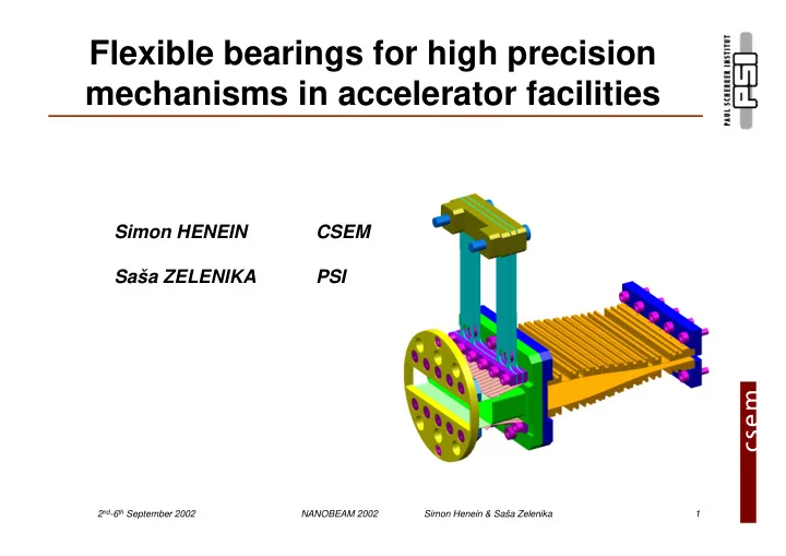
Flexible bearings for high precision mechanisms in accelerator facilities Simon HENEIN CSEM Saa ZELENIKA PSI Picture of a PSI application 2 nd -6 th September 2002 NANOBEAM 2002 Simon Henein & Saa Zelenika 1


slide-1
SLIDE 1

2nd-6th September 2002 NANOBEAM 2002 Simon Henein & Saša Zelenika 1

Flexible bearings for high precision mechanisms in accelerator facilities

Simon HENEIN CSEM Saša ZELENIKA PSI

Picture of a PSI application

slide-2
SLIDE 2

2nd-6th September 2002 NANOBEAM 2002 Simon Henein & Saša Zelenika 2

Presentation outline

  • Introduction
  • Flexible bearings design methodology

– Stroke – Parasitic movements – Restoring force – High precision mechanisms examples (CSEM)

  • Compliant mechanisms in accelerator facilities

– Why compliant mechanisms – Examples of use

  • Conclusion
slide-3
SLIDE 3

2nd-6th September 2002 NANOBEAM 2002 Simon Henein & Saša Zelenika 3

Introduction

  • Old approach
  • New needs

– extreme precision – cleanliness – hostile environments:

vacuum, cryogenic, vibrations

  • New technologies

– Electro-discharge machining – Silicon technologies, MEMs

Coach with leaf springs 1820

slide-4
SLIDE 4

2nd-6th September 2002 NANOBEAM 2002 Simon Henein & Saša Zelenika 4

Normal Stress

Tension and Compression Bending Conical spring Belleville washers Leaf springs Spiral spring Coil spring used in torsion

b h l

h l b

C

leaf spring flexible rod torsion bar

Elementary Articulations

Shear Stress

Torsion Simple Shear Coils spring Torsion bars Torsion bars

slide-5
SLIDE 5

2nd-6th September 2002 NANOBEAM 2002 Simon Henein & Saša Zelenika 5

Flexible bearings

  • High precision
  • No friction
  • No hysteresis
  • No wear
  • No lubrication
  • No risk of jamming
  • No backlash
  • Monolithic manufacturing

(“design for no assembly”)

  • Main sources of errors are

systematic => simple control laws can be used

  • Small cost
  • Limited stroke
  • Limited load capacity
  • Restoring force
  • Complex kinematics

Advantages Limitations

slide-6
SLIDE 6

2nd-6th September 2002 NANOBEAM 2002 Simon Henein & Saša Zelenika 6

Machines Robots High precision mechanisms Mechanical structures Flexible structures Flexible bearings Elementary flexible articulations

Categorisation

slide-7
SLIDE 7

2nd-6th September 2002 NANOBEAM 2002 Simon Henein & Saša Zelenika 7

Wire electro-discharge machining

  • Very small machining

forces

  • Insensitivity to hardness
  • High aspect ratios
  • High precision
  • Monolithic machining
slide-8
SLIDE 8

2nd-6th September 2002 NANOBEAM 2002 Simon Henein & Saša Zelenika 8

5 . 5 m m 25 µm 5 . 5 m m

High Aspect Ratios

slide-9
SLIDE 9

2nd-6th September 2002 NANOBEAM 2002 Simon Henein & Saša Zelenika 9

K Kt

High Stiffness Ratios

Kt K

> 20’000

slide-10
SLIDE 10

2nd-6th September 2002 NANOBEAM 2002 Simon Henein & Saša Zelenika 10

Monolithic manufacturing of complex structures

  • R. Clavel, S. Henein

ÉCOLE POLYTECHNIQUE FÉDÉRALE DE LAUSANNE

slide-11
SLIDE 11

2nd-6th September 2002 NANOBEAM 2002 Simon Henein & Saša Zelenika 11

  • N

Nn Nh

f

  • Parabola

The stiffness depends of the load N

Parallel spring stage

f P K =

P N f

slide-12
SLIDE 12

2nd-6th September 2002 NANOBEAM 2002 Simon Henein & Saša Zelenika 12

Zero stiffness flexible bearing

slide-13
SLIDE 13

2nd-6th September 2002 NANOBEAM 2002 Simon Henein & Saša Zelenika 13

P N l f x y y(x) M O

EI N S l Sl S N K = − = with 2 tan 2

Ko

Stiffness K with respect to load N

No K N

slide-14
SLIDE 14

2nd-6th September 2002 NANOBEAM 2002 Simon Henein & Saša Zelenika 14

Tuneable stiffness translation bearing

  • 1
  • 0.5

0.5 1

  • 8
  • 6
  • 4
  • 2

2 4 6 8 x [mm] F(x) [N] Force-Deformation characteristic Without compensation With compensation

slide-15
SLIDE 15

2nd-6th September 2002 NANOBEAM 2002 Simon Henein & Saša Zelenika 15

Stroke maximisation and parasitic movement compensation

a a

Bloc mobile Bloc intermédiaire Base fixe Levier de couplage

slide-16
SLIDE 16

2nd-6th September 2002 NANOBEAM 2002 Simon Henein & Saša Zelenika 16

NAOS flexible structure

rod pivot mobile pivot I/F conical pivot clamp fixed pivot I/F

slide-17
SLIDE 17

2nd-6th September 2002 NANOBEAM 2002 Simon Henein & Saša Zelenika 17

Corner Cube Mechanism for IASI instrument on METOP

slide-18
SLIDE 18

2nd-6th September 2002 NANOBEAM 2002 Simon Henein & Saša Zelenika 18

CCM main specifications

– Axial guiding for interferometer linear scanner – Displacement ± 12 mm – Lateral error off-axis <1 µm – 2.5 Hz constant velocity travel – Lifetime : 5 years non-stop (5.108 cycles)

slide-19
SLIDE 19

2nd-6th September 2002 NANOBEAM 2002 Simon Henein & Saša Zelenika 19

Why compliant mechanisms @ accelerators

  • The technological characteristics of SR and other

accelerator facilities pose severe challenges in terms of stability and reproducibility of the beam position => optical elements must be moved with resolutions and accuracies in the nm and µrad region in an UHV environment with “hostile” characteristics (thermal variations, vibrations, …)

ESRF sagittal bender now commercialised through Oxford Instruments – used also on the SLS Materials Science beamline

  • Compliant mechanisms offer

the high-precision coupled with UHV, radiation and high- or cryo-temperature compatibility

  • They are also characterized

by simple, reliable and maintenance free design

slide-20
SLIDE 20

2nd-6th September 2002 NANOBEAM 2002 Simon Henein & Saša Zelenika 20

Compliant Mechanisms Used @ SLS (1)

  • Collaboration with HASYLAB

at DESY, Hamburg (D)

  • 1st mono crystal (Si (111))

absorbs up to 1.1 kW of power (up to 3 W/mm2)

  • Elastic hinges in crystal feet

decouple it from the support structure and allow the adaptation of its shape

  • The compensation of the

convex bowing of the reflection surface induced by heat load is achieved by loading the crystal “wings”

  • The supports of the lever

arms comprise again a set of flexural elements used to achieve their longitudinal and transversal compliance

High Heat Load Monochromator Crystal Mount – Materials Science Beamline

Crystal without load Compensated crystal under load Crystal under load Heat load Heat load

slide-21
SLIDE 21

2nd-6th September 2002 NANOBEAM 2002 Simon Henein & Saša Zelenika 21

Compliant Mechanisms Used @ SLS (2)

In-Vacuum Dynamic Mirror Bender – Protein Crystallography Beamline

  • Collaboration with ESRF, Grenoble (F)
  • Vertical focusing rhodium coated fused silica mirror

placed on the same optical table and downstream of the double crystal monochromator

  • Dynamically bendable providing radiuses of

curvature in the 400-12000 m range via 2 independent bending moments at mirror ends through hysteresis-free Si-springs

  • The necessary rotational degrees of freedom and the

uncoupling of the mirror from its basement are assured through a set of EDM machined flexure hinge based joints

  • First experiences show that a sub-µrad bending

reproducibility can be obtained

slide-22
SLIDE 22

2nd-6th September 2002 NANOBEAM 2002 Simon Henein & Saša Zelenika 22

Compliant Mechanisms Used @ SLS (3)

Sagittal Crystal Bender – Protein Crystallography Beamline

  • Sagittal focusing of the second monochromator

Si (111) crystal

  • Provides an elegant way for dynamical micro-

focusing of undulator radiation in the horizontal plane

  • Bending achieved by means of 4 motorized

micrometer screws and elastic elements-based lever arms

  • First tests: at 10 keV a 6 mm beam was

focused to 20 µm with an efficiency greater than 90%

  • Dynamic focusing was also demonstrated
  • Together with the vertical focusing bender, the

micro-focusing of the beam to the designed values (10 x 25 µm2), as well as a 0.1 eV energy reproducibility of the monochromator, were reached

  • PSI patented
slide-23
SLIDE 23

2nd-6th September 2002 NANOBEAM 2002 Simon Henein & Saša Zelenika 23

Compliant Mechanisms Used @ SLS (4)

Flexible Taper Transition – In-Vacuum Undulators

  • Collaboration with Spring-8, Japan
  • A ribbon cellular CuBe structure provides a

smooth transition between the vertical aperture

  • f the adjacent fixed taper section and the in-

vacuum magnet carrying beams of the undulator, thus minimizing any impedance discontinuity

  • Shape optimized via non-linear FEM analysis

to increase fatigue lifetime

  • In a further development step longitudinal

compliance was assured via a parallel spring translator (+ a flexible-blades based transition) thus avoiding eventual axial-stresses-induced yielding due to the differential thermal expansion of the UHV chamber and the magnet carrying beams during bake-out

FLEXIBLE TAPER TRANSITION FLEXIBLE BLADES PARALLEL SPRING TRANSLATOR

slide-24
SLIDE 24

2nd-6th September 2002 NANOBEAM 2002 Simon Henein & Saša Zelenika 24

Compliant Mechanisms @ Other SR Facilities

Scanning X-ray microscope micropositioning stage, Wisconsin (USA) Mirror manipulator, Elettra, Trieste (I) Mirror bender, ESRF, Grenoble (F) High-stiffness monochromator weak- link mechanism, APS, Argonne (USA) Refocusing mirror holder, Bessy II, Berlin (D) Switching mirror flexible parallelogram, Bessy II, Berlin (D)

slide-25
SLIDE 25

2nd-6th September 2002 NANOBEAM 2002 Simon Henein & Saša Zelenika 25

Conclusion

  • Mastering the design of complex flexible structures
  • Mastering the interactions at the system level between

– Mechanical structure – Actuators – Sensors – Electronics – Control algorithms

allows to benefit from the compliant mechanisms approach in the design of accelerator equipment and instrumentation.