
SLIDE 1
PM - BEARINGS Introduction PM - BEARINGS (PM) is specialized in - - PDF document
Precision Slides PM - BEARINGS Introduction PM - BEARINGS (PM) is specialized in designing and manufacturing linear bearings in top quality. PM is providing a complete range of linear bearings, frictionless slides, positioning tables and
Since the foundation in 1966, PM has become an innova- tor in linear technology with the specialization in the pro- duction of high- and very high precision linear bearings and frictionless slides. Starting with the specialization in precision linear bearings PM has expanded and developed the linear-program through the years. Today, PM offers the widest range models and sizes to provide the designer maximum flexibility to achieve the best operating results in linear and rotary motion. One of the goals is customer-satisfaction with additional increase of productivity and reliability against lower pro- duction costs. The PM organization is dedicated to quality and is focused to give quick and accurate information on customers request. The main PM-products are published in: Linear Bearings Precision Slides Positioning Tables and Stages Linear Bearings for Unlimited Travel Subassemblies The growing market for complete subassemblies is fully sup- ported by PM and is a major part of our Total Customer Care strategy. PM is offering not only extensive assembly- facilities, skilled workers and knowledge but also a time- and cost saving solution with increase of flexilibilty in today’s rapid market. Worldwide Representation Made by PM means the same high quality, technical support and follow-ups whether in Asia, the U.S.A. or
serve you with the best technical advice and service guar- anteeing fast and reliable deliveries in all local markets. Please, contact PM for the authorized representative in your area. The specifications and data in this catalogue are believed to be accurate and reliable. However, in the interest of technical progression, PM reserves the right to modify without prior notice.
PM - BEARINGS (PM) is specialized in designing and manufacturing linear bearings in top quality. PM is providing a complete range of linear bearings, frictionless slides, positioning tables and stages, which guarantees high levels of performances at competitive prices. Thanks to a long history of experience, new findings in research, combined with innovating linear technology, PM products meet the highest accuracy and quality demands of today’s industry and are successful in use worldwide.
Progressive by innovating linear technology
Page 1 Introduction 5 Product Overview 6 Technical Data
General Friction Lubrication Effect of Elevated Temperatures Material and Hardness Linear Bearings Expected Life Wipers and Seals Maximum Velocity and Acceleration Assembly Loads and Moments Vacuum & Cleanroom Slides
11 RTN / RTL Frictionless Precision Slides 19 RTNA / RTLA Frictionless Aluminum Slides 27 RTNG Dust-Protected Precision Slides 35 RTAM Frictionless Lightweight Slides 39 RTS Frictionless Low Profile Slides 43 PMM Frictionless Miniature Slides 46 Running Accuracies 47 Special Customer Design
PM - BEARINGS frictionless slides, are ready-to-install 1-axis components for limited linear movements. The crossed roller slides use PM linear bearings type RSD, are factory pre-
extreme low uniform coefficient of friction and a long ope- ration lifetime. With various models and over a broad range
sufficient solution for each individual application in which a linear movement is required. Each type is executed with attachment holes drilled to a standard configuration to permit a quick and easy assembly in your application. Thanks to the excellent running characteristics together with the well proven reliability, these slides are today’s standard for application in the general machine industry up to high precision equipments. Special executions will be supplied according to your specifications.
Strokelengths 10-950 mm For highest accuracy performances Normal up to high load capacity Steel and cast-iron table bodies 6 sizes
Strokelengths 10-950 mm Extreme low friction resistance Setting standards in accuracy performances Aluminum table bodies 6 sizes
Strokelengths 10-250 mm Protected against dust and chips For highest accuracy performances Steel and cast-iron table bodies High rigidity
Strokelengths 25-76 mm For enhanced operation lifetime Low and compact design Aluminum table bodies 1 size and 6 lengths
Strokelengths 12-130 mm For highest accuracy performances Low profile and high rigid design Steel table bodies 3 sizes
Strokelengths 5-70 mm Ultra-compact and lightweight design For rapid and precise movements Stainless steel table bodies 3 sizes 1 4 6 5 3 2
General The PM range of linear bearings and “almost frictionless” precision slides are available in various sections with mat- ching ball- and roller diameter in a wide range of standard lengths. The choice of sizes (cross-sections) and lengths caters for almost all load capacities, enabling the designer to solve most linear motion problems with virtual frictionfree movements, free from play, with adjustable pre-load. Due to these features PM linear bearings are almost complete free from wear, needing only minimum lubrication and maintenance, and are used successfully in a wide range of industries, e.g.: Packing machinery Machine tools + other metal working machinery Automation applications Special purpose machines + special purpose tooling Due to the high linear accuracy, which PM linear bearings
Measuring instruments Tool setting equipments Robotic devices Space applications Research projects Semiconductor equipments To sum up, PM’s full assembled frictionless linear slides, have a compact size, offer facility of installation, high accuracy of running motion, long life with only minimal lubrication, low maintenance costs, and ease of replacement in the event of
vital components in the application they are manufactured with the greatest care to provide the maximum of linear accuracy and reliability that is likely to be required. Friction PM frictionless slides give an unprecedented friction coefficient of <0.003. Through this, the characteristics of the linear slides in combination with a correct mounting and lubrication find the best way for expression. Friction is the force necessary to move a body along a horizontal plane or track. A fine machined surface gives a positive effect on the friction. Therefore PM is using the highest quality of roller bodies in combination with precision ground anti-friction guideways type RSD which are manufactured by a team of specialists. Compared with
rollers offer not only much lower frictional resistance, but also an almost complete absence of static friction. µ = Coefficient of friction Fn = Normal force F = Frictional resistance Note: wipers and seals give a negative reaction on the friction. Lubrication PM precision guides and slides are a main part in the construction of machines. The standardized high quality has to be secured during the calculated lifetime. Nevertheless dust and moisture are the main enemies of the precision
surfaces and gives a sufficient protection against corrosion. Other benefits are for example: Friction reduction Reduction of wear Prolongation of lifetime Transport of heat We prefer lubrication by oil CLP like DIN 51519 and HLP like DIN 51524. During operation the temperature has to be between -30°C till +120°C while the viscosity is between ISO-VG15 and ISO-VG100. Frictionless slides will be supplied with a sufficient oil lubrication. This lubrication, depending on the condition of use and the environment, will be working for years. However, experience has shown that a regular lubrication has a positive effect on the
guides which are manufactured of not standardized materials or used in special operation environments the lubrication has to be taken into account. For further infor- mation, please contact PM - BEARINGS.
Effect of Elevated Temperatures PM slides can be used by temperatures between -40°C up to +80°C during operation. In case of doubt or questions by the use of motors, ball screws, measuring systems etc. please consult PM - BEARINGS. When PM linear bearings are used at temperatures in excess of 150 °C, the track-rail hardness begins to fall off and the load ratings must be reduced in accordance with factor ft, tabulated below. If different elements of a linear bearing assembly, which has been pre-loaded or adjusted for freedom of play, suffers differential temperatures, then this could have harmful effects. In the worst case, the pre-load can become excessive and cause Brinnel-type indentations in the bearing ways. Accordingly, if high demands are placed on running accuracy, then such temperature differentials must be avoided. Material and Hardness Linear Bearings The guideways are manufactured of bearing steel 1.2842
cylindrical rollers and balls are made of bearing steel 1.3505 with an hardness value of 58-66 Hrc, and are used in the highest grade quality. Only in cases, where the hardness is less than 58 Hrc (as for rust-resisting steels) the rated loads have to be reduced in accordance with the hardness factor fh, tabulated. Load ratings, which are quoted in this catalog, actually refer to a Rockwell hardness of 58 Hrc. Expected Life To estimate the expected life for linear bearings the following calculation can be employed, providing that the recommended installation conditions, lubrication, and protection from dust and dirt are maintained. L= (C/P)e x 1,15 x ft x fh x 105 metres L = expected life in metres. C = effective dynamic load rating in N. P = equivalent load in N. e = 10/3 for rollers and needle rollers, and 3 for balls. 1,15 = an empirical factor applicable to the materials employed. ft = correction factor for temperature effects. (see above) fh = correction factor for guideway hardness grades. (i.e.: below 58 Hrc)
Hardness Hardness Rockwell Hrc. Vickers HV Brinell HB factor fh
60 697
59 674
58 653
57 633
56 613
55 595
54 577
53 560
52 544 500 0.67 51 528 487 0.63 50 513 475 0.60 Temperature in °C Temperature factor ft 125 1 150 1 175 0.95 200 0.90 225 0.82 250 0.76 275 0.68 300 0.61 Fahrenheit: 1 deg F= 0.5556 °C
Wipers and Seals Whenever our linear bearings are installed under unfavou- rable ambient conditions, it is advisable to protect them from the ingress of dust and dirt. For anti-friction guideways type RSD, RSDE, N+O/M+V special endstops with felt-wipers can be supplied, optional to order. There are also fully enclosed RTNG-slides, with a small air-gap which acts as a seal (the necessary extension of the slide-base results in a considerable increase in length compared with standard units). For other sealing arrangements, or wipers, please enquire PM - BEARINGS. Maximum Velocity and Acceleration RSD + RSDE series linear bearings:
N+O type linear bearings:
(depending on type of bearing-cage used) To attain maximum acceleration and speeds without skidding of balls or rollers (which can result in cage creeping) the bearings must be suitable pre-loaded (for details please enquire). For higher accelerations and dynamics with our slide tables we provide modifications, please enquire PM-Bearings. Assembly The mounting holes of each type are drilled to a standard configuration in slide-top and -base and permit the user a quick attachment into the application. Thread holes in the table parts are according to ISO-standard. Dimensions in this catalogue are in mm. PM linear slides are precision devices and require proper mounting to perform at rated specifications. They have to be mounted on rigid and fine-machined, preferable by fine-mil- ling, flat surfaces and supported over their entire base
slide will be shown to full advantage. Loads and Moments The slides listed in this catalogue are able to carry loads and moments in any direction. The load ratings are based
calculation of roller bearings (ISO standard 281, for minia- ture slide type PMM DIN 636, part 3). To ensure the high running accuracy and to prevent against play, vibration and
defined in ISO76-1987, is the maximum downward load
zero-position. Moment Load: the max. allowable moment load capacities listed in this catalog are created in three orientations Ml = pitch moment: when a load is cantilevered (not sym- metrically mounted) off the end of an axis, parallel to the direction of travel. Md = roll moment: when a load is cantilevered off the side
Mr = yaw moment: when a force causes a rotation moment about the center of an axis. Exceeding of the listed moment ratings may reduce the life
to contact one of our product specialists for more informa- tion. Vacuum and Cleanroom Compatible Slides Most of the PM slides can be prepared for use in (ultra- high) vacuum or cleanroom environments. Special care has to be taken for example with the selection of the low outgassing materials, special lubricants, surface finishings, vented stain- less steel fasteners for use in blind tapped holes, special ball- or crossed rollercages and with the selection of switches and wires. For the assembly of the tables we use modern clean-room cells upto ISO/FDIS 14644-1 class 5 with cleanspots class 3. With over 35 years experience in this field we are ready to meet the most challenging requirements. For more information please consult PM.
NEW QUALITY GRADE SF-CLASS FOR LINEAR BEARINGS OFFERS MAXIMUM PERFORMANCE
Dedemsvaart – The Netherlands, September 6, 1999 PM – BEARINGS BV (PM) announces a new innovative quality grade for their crossed roller bearings – Option SF-class. SF-Class (Super Finish) is used in certain opti- cal and electronic scanning applications where vibrations can affect the reading of accuracy of the system. Other applications are fiber optic splicing equipments and wire bonding stages which require the highest class in accuracy and reliability. SF class offers a runout of no more than 2 micron over a travel distance of 1200mm. The highly polished V-grooves provide the smoothest motion of any mechanical bearing system together with an extremely consistent virtually zero frictional force, which make this bearing well suited for applications where a precise reading of axial force must be obtained. The surface roughness of the V-grooves is less than 0.05 Ra instead of conventional guides with 0.1Ra. PM ’s SF-class can provide linear travel in sub-micron range and is now available in all precision crossed roller slides and positioning tables. PM is a leading manufacturer of high precision linear bearings, slides and stages. Their products are meeting the highest accuracy and quality demands of today’s industry and are successful in use worldwide. The wide range of products offers designers maximum flexibility to match every requirement in linear and rotary motion applications. For more information: PM – BEARINGS BV Phone: +31 (0)523 612 258 Fax:+31 (0)523 615 290 Website: www.pmbearings.nl
Material Table Bodies Size Ø1.5, Ø2, Ø3mm and Ø4mm: steel, black oxide finish. Size Ø6 and Ø9mm: cast-iron, black oxide finish. Features and Specifications Incorporates pre-loaded linear bearings type RSD and double-side track-rail, including roller cages. Slide-top and -base have equal lengths. 2 standard strokelengths (N- and L-stroke). Linear strokes are limited by internal mounted end-stops, two in the slide-top and one or two in the base-plate, depending on RTL or RTN version. N-stroke: for normal stroke/travel, with normal loads L-stroke: for longer stroke/travel, with reduced loads Size Ø1.5 and Ø2 mm: use in each direction (with brass roller cage type CC). Size Ø3, Ø4, Ø6 (pitch t=9mm) and Ø9mm (pitch t=14mm): horizontal fitting model (with steel roller cage type AA). Vertical fitting model (with brass roller cage type DD). All mounting surfaces are precision ground. One flank of the slide ( the side opposite to the adjust- ment screws) is ground parallel to the linear bearings to serve as a Reference Face. The slide-top is provided with tapped attachment holes, drilled to a standard configuration. The slide-base is equipped with countersunk-bored holes, which accept sockethead screws. Running accuracies are shown on page 46. Options Selected slides can be supplied with an height tolerance of ±0.01 mm. Cages can be replaced by plastic crossed roller cages type KZR or type KKLK for balls. Higher accuracy grade slides. Stainless steel version. SF-Class technology for maximum performance. High vacuum modification. Notes by ordering By ordering please specify the following:
“in between”, only size Ø3, Ø4, Ø6 and Ø9mm). Example: 1 piece slide type RTN-3250-Vert. PM frictionless precision slides type RTN and RTL are pre-loaded linear motion components, ready for mounting. The well proven design of this model offers a wide range of benefits as for example; high rigidity, no stick-slib effect and an unprecedented precision in linear movement thanks to the installation of a double-sided track-rail on the slide-base which eliminates machining errors on the slide-base.
Travel H Type A B C D RTN RTL f f1 g g1 h h1 h2 m m1 m2 RT- 1520 25 10
35 15 20 2 x 10 1 x 10 RT- 1540 45 20 30 3 x 10 2 x 10 RT- 1550 55 25 40 4 x 10 3 x 10 RT- 1560 65 29.6 17 1.5 30 50 7.5 12.5 5 x 10 4 x 10 10 18.4 12 M2.5 M2 M2 RT- 1570 75 35 60 6 x 10 5 x 10 RT- 1580 85 40 70 7 x 10 6 x 10 RT- 1590 95 45 80 8 x 10 7 x 10 RT-15100 105 50 90 9 x 10 8 x 10 RT- 2030 35 15
50 22 30 2 x 15 1 x 15 RT- 2060 65 30 45 3 x 15 2 x 15 RT- 2075 80 37 60 4 x 15 3 x 15 RT- 2090 95 39.6 21 2 45 75 10 17.5 5 x 15 4 x 15 15 25 16 M3 M2.5 M2 RT- 2105 110 52 90 6 x 15 5 x 15 RT- 2120 125 60 105 7 x 15 6 x 15 RT- 2135 140 67 120 8 x 15 7 x 15 RT- 2150 155 75 135 9 x 15 8 x 15 RT- 3050 55
1 x 25
80 37 55 2 x 25 1 x 25 RT- 3100 105 50 80 3 x 25 2 x 25 RT- 3125 130 62 105 4 x 25 3 x 25 RT- 3150 155 75 130 5 x 25 4 x 25 RT- 3175 180 59.5 28 3 87 155 15 27.5 6 x 25 5 x 25 25 41 40 M4 M4 M3 RT- 3200 205 100 180 7 x 25 6 x 25 RT- 3250 255 125 230 9 x 25 8 x 25 RT- 3300 305 150 280 11 x 25 10 x 25 RT- 3350 355 175 330 13 x 25 12 x 25 RT- 3400 405 200 380 15 x 25 14 x 25
Layout mounting holes slide-base at page 16
C in N Weight Md in Nm Ml in Nm Mr in Nm n p s t v x y 2.45 260
1.4
312 0.12 2.1 2.1 2.5 1.9 1.9 1.7 520 416 0.16 3.5 2.8 4.4 3.1 2.6 2.1 624 520 0.19 4.2 3.5 5.6 4.4 3.1 2.6 2.5 4.6 6 3.7 4.5 13.5 8.75 780 572 0.23 4.9 3.5 7.5 5.0 4.0 2.9 884 676 0.27 5.6 4.2 8.7 6.2 4.6 3.4 1040 780 0.30 7.0 4.9 10.6 7.5 5.5 4.0 1144 832 0.34 7.7 5.6 11.9 8.1 6.1 4.3 1300 936 0.37 8.4 6.3 13.7 9.4 7.0 4.9 430
3.1
602 0.28 6.2 4.6 6.9 5.5 4.6 4.1 946 774 0.38 7.7 6.2 11.0 8.3 6.3 5.2 1204 946 0.47 10.8 7.7 15.1 11.0 8.2 6.3 3.4 6.3 7 5.5 5.5 18 10.75 1376 1118 0.56 12.4 9.3 17.9 13.8 9.5 7.5 1634 1290 0.65 13.9 10.8 22.0 16.5 11.4 8.8 1892 1376 0.75 17.0 12.4 26.1 17.9 13.4 9.5 2150 1548 0.84 18.6 13.9 30.3 20.6 15.4 10.8 2408 1720 0.93 21.7 15.5 34.4 23.4 17.5 12.1
0.64
1496 1224 0.94 20.4 16.3 21.8 16.3 13.6 11.5 2040 1632 1.24 28.6 24.5 32.6 24.5 18.2 14.7 2448 1904 1.55 36.7 28.6 40.8 29.9 22.0 17.0 2992 2312 1.86 44.9 32.6 51.7 38.1 27.1 20.7 5.5 7.8 9.5 5.5 8 30 14 3536 2584 2.15 53.0 36.7 62.6 43.5 32.3 23.2 4080 2992 2.46 61.2 44.9 73.4 51.7 37.6 27.1 5032 3672 3.06 73.4 53.0 92.5 65.3 47.0 33.6 6120 4352 3.66 89.8 65.3 114.2 78.9 57.7 40.3 7072 5032 4.27 106.1 73.4 133.3 92.5 67.1 47.0 8160 5712 4.87 122.4 85.7 155.0 106.1 77.9 53.7 RTN RTL RTN RTL RTN RTL RTN RTL in Kg
Travel H Type A B C D RTN RTL f f1 g g1 h h1 h2 h3 m m1 RT- 4080 85 50
125 75 90 2 x 40 1 x 40 RT- 4160 165 105 130 3 x 40 2 x 40 RT- 4200 205 130 170 4 x 40 3 x 40 RT- 4240 245 80 35 4 155 210 22.5 42.5 5 x 40 4 x 40 40 53 55
M5 RT- 4280 285 185 250 6 x 40 5 x 40 RT- 4320 325 210 290 7 x 40 6 x 40 RT- 4360 365 235 330 8 x 40 7 x 40 RT- 4400 405 265 370 9 x 40 8 x 40 RT- 6100 110 50 70 1 x 50
160 75 120 2 x 50 1 x 50 RT- 6200 210 100 170 3 x 50 2 x 50 RT- 6250 260 125 220 4 x 50 3 x 50 RT- 6300 310 150 270 5 x 50 4 x 50 RT- 6350 360 99.5 45 6 175 320 30 55 6 x 50 5 x 50 50 65 60 92 M6 M6 RT- 6400 410 200 370 7 x 50 6 x 50 RT- 6450 460 225 420 8 x 50 7 x 50 RT- 6500 510 250 470 9 x 50 8 x 50 RT- 6600 610 300 570 11 x 50 10 x 50 RT- 6700 710 350 670 13 x 50 12 x 50 RT- 9100 110 50
55 1 x 50
210 100 150 1 x 100
310 150 250 2 x 100 1 x 100 RT- 9400 410 200 350 3 x 100 2 x 100 RT- 9500 510 148 60 9 250 450 55 105 4 x 100 3 x 100 100 104 90 135 M8 M8 RT- 9600 610 300 550 5 x 100 4 x 100 RT- 9700 710 350 650 6 x 100 5 x 100 RT- 9800 810 400 750 7 x 100 6 x 100 RT- 9900 910 450 850 8 x 100 7 x 100 RT- 91000 1010 500 950 9 x 100 8 x 100
x g g g f f t t m1 m1 f1 g1 g1 f1 p v h2 n y n1 h3 H H
A
D m2
B
h1 h m
Layout mounting holes slide-base at page 17
C in N Weight Md in Nm Ml in Nm Mr in Nm m2 n n1 p s t v x y 1855
31.8
2650 2.50 53.0 53.0 59.4 51.9 36.5 33.5 3710 3445 3.30 74.2 63.6 81.6 74.2 46.0 42.7 4770 4240 4.10 95.4 84.8 111.3 96.5 59.6 52.7 M3 6.5
9 9.5 40 18.5 5830 4770 4.90 116.6 95.4 141.0 111.3 73.6 59.6 6890 5565 5.70 137.8 106.0 170.7 133.6 87.9 70.1 7950 6360 6.50 159.0 127.2 200.3 155.8 102.4 80.7 9010 7155 7.30 180.2 137.8 230.0 178.1 116.9 91.5 9805 7950 8.10 190.8 159.0 252.3 200.3 127.9 102.4 4320 3780 3.30 97.2 72.9 97.2 77.8 68.7 62.2 6480 5400 4.84 145.8 121.5 175.0 136.1 100.1 83.6 8640 6480 6.37 194.4 145.8 252.7 175.0 135.4 100.1 10800 8100 7.91 243.0 170.1 330.5 233.3 172.2 126.4 13500 9720 9.44 291.6 218.7 427.7 291.6 219.3 153.7 M4 8 15 11 14 10 11 46 23 15660 11340 11.00 340.2 243.0 505.4 349.9 257.4 181.6 17820 12420 12.54 388.8 267.3 583.2 388.8 295.6 200.4 19980 14040 14.07 437.4 315.9 661.0 447.1 334.0 228.8 22140 15660 15.60 486.0 340.2 738.7 505.4 372.5 257.4 27000 18900 18.65 607.5 413.1 913.7 622.1 459.4 314.8 31320 21600 21.71 704.7 486.0 1069.2 719.3 536.8 362.9 6750
210.6
526.5 421.2 529.2 378.0 338.2 283.0 21600 16200 18.86 842.4 631.8 982.8 680.4 534.6 400.1 28350 21600 25.08 1053.0 842.4 1360.8 982.8 712.2 534.6 M4 11 20 14 17 17 14 78 31 35100 25650 31.20 1368.9 947.7 1738.8 1209.6 894.5 640.4 43200 31050 37.41 1684.8 1158.3 2192.4 1512.0 1116.2 784.8 49950 35100 43.53 1895.4 1368.9 2570.4 1738.8 1302.3 894.5 56700 40500 49.75 2211.3 1579.5 2948.4 2041.2 1489.2 1042.1 64800 44550 55.96 2527.2 1684.8 3402.0 2268.0 1714.0 1153.4 71550 49950 62.08 2737.8 1895.4 3780.0 2570.4 1901.7 1302.3 RTN RTL RTN RTL RTN RTL RTN RTL in Kg
Type A B c d e f g k p r Fig. RT- 1520 25 17
RT- 1530 35 27
RT- 1540 45 37
RT- 1550 55 47
RT- 1560 65 29.6 22 57
5 2.5 2 RT- 1570 75 67
RT- 1580 85 77
RT- 1590 95 87
RT- 15100 105 97
RT- 2030 35 25
RT- 2045 50 40
RT- 2060 65 55
RT- 2075 80 70
RT- 2090 95 85
RT- 2105 110 39.6 30 100
6.3 3.3 2 RT- 2120 125 115
RT- 2135 140 130
RT- 2150 155 145
RT- 3050 55 35
RT- 3075 80 60
RT- 3100 105 85
RT- 3125 130 110
RT- 3150 155 135
RT- 3175 180 59.5 40 160
7.8 4.3 2 RT- 3200 205 185
RT- 3250 255 235 145 55
RT- 3300 305 285 165 65
RT- 3350 355 335 195 75
RT- 3400 405 385 225 85
mm
Layout mounting holes slide-base
Type A B c d e f g k p r Fig. RT- 4080 85 65
RT- 4120 125 105
RT- 4160 165 145
RT- 4200 205 185
RT- 4240 245 80 55 225
10 5.4 2 RT- 4280 285 265
RT- 4320 325 305 145 225
RT- 4360 365 345 185 265
RT- 4400 405 385 225 305
RT- 6100 110 90
RT- 6150 160 140
RT- 6200 210 190
RT- 6250 260 240
RT- 6300 310 290
RT- 6350 360 99.5 60 340 200 80
11 6.3 3 RT- 6400 410 390 230 90
RT- 6450 460 440 260 100
RT- 6500 510 490 290 110
RT- 6600 610 590 350 210 70 4 RT- 6700 710 690 410 250 90 4 RT- 9100 110 80
RT- 9200 210 100
RT- 9300 310 200
RT- 9400 410 300
RT- 9500 510 148 90 400
14 8.7 2 RT- 9600 610 500 340 120
RT- 9700 710 600 400 140
RT- 9800 810 700 460 280 100 4 RT- 9900 910 800 520 320 120 4 RT- 91000 1010 900 600 360 120 4 mm
Layout mounting holes slide-base
PM LINEAR BEARINGS AND TABLES NOW AVAILABLE WITH THE FIRST STANDARDIZED ANTI-CAGE CREEP SOLUTION
Dedemsvaart – The Netherlands, February 21, 2001 PM – BEARINGS BV (PM) announces the introduction of the first standardized Anti-Cage Creep (ACC) option for their crossed roller bearings RSDE and frictionless crossed roller tables (slides). Cage creep can occur in non-recirculating linear bearing applications where vibrations, improper mounting, very high-acceleration and de- acceleration, inadequate tolerances on the mounting surfaces, uneven preload or moment loading are
The ACC option is designed for use in high-tech and extreme dynamic applications like wire bonding tables and pick and place units. It has proven ability to prevent cage creeping in the most demanding applications and the most severe test environment conditions. The ACC option is an all metal design and is integrated in the design of the linear bearing without influencing the external boundary or mounting
by the ACC option without any machine modification. ACC can operate under temperatures of -40°C up to +80°C which is a significant advantage over similar systems using plastic components. This also makes it suitable for vacuum applications.
PM ’s ACC option can provide linear travel in micron range with virtually zero friction and is now available in precision crossed roller bearings RSDE in sizes 3, 4, 6 and 9mm. PM is a leading manufacturer of high precision linear bearings, slides and stages. Their products are meeting the highest accuracy and quality demands of today’s industry and are successful in use
linear and rotary motion applications. For more information: PM – BEARINGS BV Phone: +31 (0)523 612 258 Fax:+31 (0)523 615 290 Website: www.pmbearings.nl
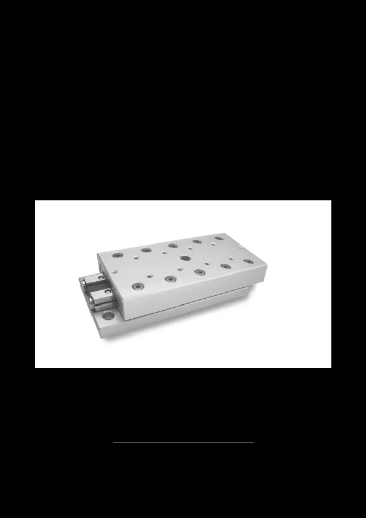
Material Table Bodies Aluminum, clear anodized finishing. Features and Specifications Incorporates pre-loaded linear bearings type RSD and double-sided track-rail, including roller cages. Slide-top and -base have equal lengths. 2 standard strokelengths (N- and L-stroke). Linear strokes are limited by internal mounted end- stops, two in the slide-top and one or two in the base- plate, depending on RTLA or RTNA version. N-stroke: for normal stroke/travel, with normal loads. L-stroke: for longer stroke/travel, with reduced loads. Size Ø1.5 and Ø2 mm: use in each direction (with brass roller cage type CC). Size Ø3, Ø4, Ø6 (pitch t=9 mm) and Ø9mm (pitch t=14mm), horizontal fitting model (with steel roller cage type AA). Vertical fitting model (with brass roller cage type DD). All mounting surfaces are precision ground. One flank of the slide ( the side opposite to the adjust ment screws) is ground parallel to the linear bearings to serve as a Reference Face. The slide-top is provided with tapped attachment holes, drilled to a standard configuration. The slide-base is equipped with countersunk-bored holes, which accept sockethead screws. Running accuracies are shown on page 46. Options Cages can be replaced by plastic crossed roller cages type KZR or type KKLK fitted with balls. Higher accuracy grade slides. Stainless steel version. SF-Class technology for maximum performance. High vacuum modification. Notes by ordering By ordering please specify the following:
between”, only size Ø3, Ø4, Ø6 and Ø9mm). Example: 1 piece slide type RTNA-3250-Vert. PM frictionless slides type RTNA and RTLA are fine pre-loaded linear motion components, ready for mounting. Mainly made in aluminum, this model offers a wide range of benefits as for example; low weight, no stick-slib effect and easy to mount into the
Travel H Type A B C D RTNA RTLA f f1 g g1 h h1 h2 m m1 m2 RTA- 1520 25 10
35 15 20 2 x 10 1 x 10 RTA- 1540 45 20 30 3 x 10 2 x 10 RTA- 1550 55 25 40 4 x 10 3 x 10 RTA- 1560 65 30 15 1.5 30 50 7.5 12.5 5 x 10 4 x 10 10 18.4 12 M2.5 M2 M2 RTA- 1570 75 35 60 6 x 10 5 x 10 RTA- 1580 85 40 70 7 x 10 6 x 10 RTA- 1590 95 45 80 8 x 10 7 x 10 RTA-15100 105 50 90 9 x 10 8 x 10 RTA- 2030 35 15
50 22 30 2 x 15 1 x 15 RTA- 2060 65 30 45 3 x 15 2 x 15 RTA- 2075 80 37 60 4 x 15 3 x 15 RTA- 2090 95 40 21 2 45 75 10 17.5 5 x 15 4 x 15 15 25 16 M3 M2.5 M2 RTA- 2105 110 52 90 6 x 15 5 x 15 RTA- 2120 125 60 105 7 x 15 6 x 15 RTA- 2135 140 67 120 8 x 15 7 x 15 RTA- 2150 155 75 135 9 x 15 8 x 15 RTA- 3050 55
1 x 25
80 37 55 2 x 25 1 x 25 RTA- 3100 105 50 80 3 x 25 2 x 25 RTA- 3125 130 62 105 4 x 25 3 x 25 RTA- 3150 155 75 130 5 x 25 4 x 25 RTA- 3175 180 60 25 3 87 155 15 27.5 6 x 25 5 x 25 25 41 40 M4 M4 M3 RTA- 3200 205 100 180 7 x 25 6 x 25 RTA- 3250 255 125 230 9 x 25 8 x 25 RTA- 3300 305 150 280 11 x 25 10 x 25 RTA- 3350 355 175 330 13 x 25 12 x 25 RTA- 3400 405 200 380 15 x 25 14 x 25 mm
Layout mounting holes slide-base at page 24
C in N Weight Md in Nm Ml in Nm Mr in Nm n p s t v x y 2.45 260
1.4
312 0.05 2.1 2.1 2.5 1.9 1.9 1.7 520 416 0.06 3.5 2.8 4.4 3.1 2.6 2.1 624 520 0.08 4.2 3.5 5.6 4.4 3.1 2.6 2.5 4.6 5.25 3.7 4.5 13.5 7.5 780 572 0.09 4.9 3.5 7.5 5.0 4.0 2.9 884 676 0.11 5.6 4.2 8.7 6.2 4.6 3.4 1040 780 0.12 7.0 4.9 10.6 7.5 5.5 4.0 1144 832 0.13 7.7 5.6 11.9 8.1 6.1 4.3 1300 936 0.15 8.4 6.3 13.7 9.4 7.0 4.9 430
3.1
602 0.15 6.2 4.6 6.9 5.5 4.6 4.1 946 774 0.19 7.7 6.2 11.0 8.3 6.3 5.2 1204 946 0.24 10.8 7.7 15.1 11.0 8.2 6.3 3.4 6.3 7 5.5 5.5 18 10.75 1376 1118 0.28 12.4 9.3 17.9 13.8 9.5 7.5 1634 1290 0.33 13.9 10.8 22.0 16.5 11.4 8.8 1892 1376 0.37 17.0 12.4 26.1 17.9 13.4 9.5 2150 1548 0.42 18.6 13.9 30.3 20.6 15.4 10.8 2408 1720 0.46 21.7 15.5 34.4 23.4 17.5 12.1
0.30
1496 1224 0.44 20.4 16.3 21.8 16.3 13.6 11.5 2040 1632 0.58 28.6 24.5 32.6 24.5 18.2 14.7 2448 1904 0.72 36.7 28.6 40.8 29.9 22.0 17.0 2992 2312 0.85 44.9 32.6 51.7 38.1 27.1 20.7 5.5 7.8 8.25 5.5 8 30 12.25 3536 2584 0.99 53.0 36.7 62.6 43.5 32.3 23.2 4080 2992 1.13 61.2 44.9 73.4 51.7 37.6 27.1 5032 3672 1.41 73.4 53.0 92.5 65.3 47.0 33.6 6120 4352 1.68 89.8 65.3 114.2 78.9 57.7 40.3 7072 5032 1.97 106.1 73.4 133.3 92.5 67.1 47.0 8160 5712 2.15 122.4 85.7 155.0 106.1 77.9 53.7 RTNA RTLA RTNA RTLA RTNA RTLA RTNA RTLA in Kg
Travel H Type A B C D RTNA RTLA f f1 g g1 h h1 h2 h3 m m1 RTA- 4080 85 50
125 75 90 2 x 40 1 x 40 RTA- 4160 165 105 130 3 x 40 2 x 40 RTA- 4200 205 130 170 4 x 40 3 x 40 RTA- 4240 245 80 35 4 155 210 22.5 42.5 5 x 40 4 x 40 40 53 55
M5 RTA- 4280 285 185 250 6 x 40 5 x 40 RTA- 4320 325 210 290 7 x 40 6 x 40 RTA- 4360 365 235 330 8 x 40 7 x 40 RTA- 4400 405 265 370 9 x 40 8 x 40 RTA- 6100 110 50 70 1 x 50
160 75 120 2 x 50 1 x 50 RTA- 6200 210 100 170 3 x 50 2 x 50 RTA- 6250 260 125 220 4 x 50 3 x 50 RTA- 6300 310 150 270 5 x 50 4 x 50 RTA- 6350 360 100 40 6 175 320 30 55 6 x 50 5 x 50 50 65 60 92 M6 M6 RTA- 6400 410 200 370 7 x 50 6 x 50 RTA- 6450 460 225 420 8 x 50 7 x 50 RTA- 6500 510 250 470 9 x 50 8 x 50 RTA- 6600 610 300 570 11 x 50 10 x 50 RTA- 6700 710 350 670 13 x 50 12 x 50 RTA- 9100 110 50
55 1 x 50
210 100 150 1 x 100
310 150 250 2 x 100 1 x 100 RTA- 9400 410 200 350 3 x 100 2 x 100 RTA- 9500 510 148.4 60 9 250 450 55 105 4 x 100 3 x 100 100 104 90 135 M8 M8 RTA- 9600 610 300 550 5 x 100 4 x 100 RTA- 9700 710 350 650 6 x 100 5 x 100 RTA- 9800 810 400 750 7 x 100 6 x 100 RTA- 9900 910 450 850 8 x 100 7 x 100 RTA- 91000 1010 500 950 9 x 100 8 x 100 mm
x g g g f f t t m1 m1 f1 g1 g1 f1 p v h2 n y n1 h3 H H
A
D m2
B
h1 h m
Layout mounting holes slide-base at page 25
C in N Weight Md in Nm Ml in Nm Mr in Nm m2 n n1 p s t v x y 1855
31.8
2650 1.14 53.0 53.0 59.4 51.9 36.5 33.5 3710 3445 1.51 74.2 63.6 81.6 74.2 46.0 42.7 4770 4240 1.87 95.4 84.8 111.3 96.5 59.6 52.7 M3 6.5
9 9.5 40 18.5 5830 4770 2.24 116.6 95.4 141.0 111.3 73.6 59.6 6890 5565 2.60 137.8 106.0 170.7 133.6 87.9 70.1 7950 6360 3.00 159.0 127.2 200.3 155.8 102.4 80.7 9010 7155 3.30 180.2 137.8 230.0 178.1 116.9 91.5 9805 7950 3.70 190.8 159.0 252.3 200.3 127.9 102.4 4320 3780 1.65 97.2 72.9 97.2 77.8 68.7 62.2 6480 5400 2.43 145.8 121.5 175.0 136.1 100.1 83.6 8640 6480 3.20 194.4 145.8 252.7 175.0 135.4 100.1 10800 8100 3.98 243.0 170.1 330.5 233.3 172.2 126.4 13500 9720 4.75 291.6 218.7 427.7 291.6 219.3 153.7 M4 8 15 11 12 10 11 46 20 15660 11340 5.52 340.2 243.0 505.4 349.9 257.4 181.6 17820 12420 6.30 388.8 267.3 583.2 388.8 295.6 200.4 19980 14040 7.07 437.4 315.9 661.0 447.1 334.0 228.8 22140 15660 7.86 486.0 340.2 738.7 505.4 372.5 257.4 27000 18900 9.41 607.5 413.1 913.7 622.1 459.4 314.8 31320 21600 10.91 704.7 486.0 1069.2 719.3 536.8 362.9 6750
210.6
6.92 526.5 421.2 529.2 378.0 338.2 283.0 21600 16200 10.50 842.4 631.8 982.8 680.4 534.6 400.1 28350 21600 14.17 1053.0 842.4 1360.8 982.8 712.2 534.6 M4 11 20 14 17 17 14 78 31 35100 25650 17.84 1368.9 947.7 1738.8 1209.6 894.5 640.4 43200 31050 21.51 1684.8 1158.3 2192.4 1512.0 1116.2 784.8 49950 35100 25.18 1895.4 1368.9 2570.4 1738.8 1302.3 894.5 56700 40500 28.95 2211.3 1579.5 2948.4 2041.2 1489.2 1042.1 64800 44550 32.52 2527.2 1684.8 3402.0 2268.0 1714.0 1153.4 71550 49950 35.98 2737.8 1895.4 3780.0 2570.4 1901.7 1302.3 RTNA RTLA RTNA RTLA RTNA RTLA RTNA RTLA in Kg
Layout mounting holes slide-base
Type A B c d e f g k p r Fig. RTA- 1520 25 17
RTA- 1530 35 27
RTA- 1540 45 37
RTA- 1550 55 47
RTA- 1560 65 30 22 57
5 2.5 2 RTA- 1570 75 67
RTA- 1580 85 77
RTA- 1590 95 87
RTA- 15100 105 97
RTA- 2030 35 25
RTA- 2045 50 40
RTA- 2060 65 55
RTA- 2075 80 70
RTA- 2090 95 85
RTA- 2105 110 40 30 100
6.3 3.3 2 RTA- 2120 125 115
RTA- 2135 140 130
RTA- 2150 155 145
RTA- 3050 55 35
RTA- 3075 80 60
RTA- 3100 105 85
RTA- 3125 130 110
RTA- 3150 155 135
RTA- 3175 180 60 40 160
7.8 4.3 2 RTA- 3200 205 185
RTA- 3250 255 235 145 55
RTA- 3300 305 285 165 65
RTA- 3350 355 335 195 75
RTA- 3400 405 385 225 85
mm
Type A B c d e f g k p r Fig. RTA- 4080 85 65
RTA- 4120 125 105
RTA- 4160 165 145
RTA- 4200 205 185
RTA- 4240 245 80 55 225
10 5.4 2 RTA- 4280 285 265
RTA- 4320 325 305 145 225
RTA- 4360 365 345 185 265
RTA- 4400 405 385 225 305
RTA- 6100 110 90
RTA- 6150 160 140
RTA- 6200 210 190
RTA- 6250 260 240
RTA- 6300 310 290
RTA- 6350 360 100 60 340 200 80
11 6.3 3 RTA- 6400 410 390 230 90
RTA- 6450 460 440 260 100
RTA- 6500 510 490 290 110
RTA- 6600 610 590 350 210 70 4 RTA- 6700 710 690 410 250 90 4 RTA- 9100 110 80
RTA- 9200 210 100
RTA- 9300 310 200
RTA- 9400 410 300
RTA- 9500 510 148.4 90 400
14 8.7 2 RTA- 9600 610 500 340 120
RTA- 9700 710 600 400 140
RTA- 9800 810 700 460 280 100 4 RTA- 9900 910 800 520 320 120 4 RTA- 91000 1010 900 600 360 120 4 mm
Layout mounting holes slide-base
Material Table Bodies Size Ø1.5, Ø2 and Ø3mm: steel, black oxide finish. Size Ø6 and Ø9mm: cast-iron, black oxide finish Features and Specifications Incorporates pre-loaded linear bearings type RSD and double-sided track-rail, including roller cages. Linear strokes are limited by the endplates. It is not per- mitted to use this plates as machine endstops. Roller cage: Size Ø1.5 and Ø2 mm: type CC Size Ø3, Ø6 (pitch t=9 mm) and Ø9mm (pitch t=14mm): type DD. Can be mounted in horizontal and vertical direction. Air gab (0.08 mm approx.) between slide-top and base. All mounting surfaces are precision ground. One flank of the slide (the side opposite to the adjust- ment screws) is ground parallel to the linear bearings to serve as a Reference Face. The slide-top and - base are equipped with tapped attachment holes, drilled to a standard configuration. Running accuracies are shown on page 46. Options
with dust protected wipers and seals for full covering, as showed on top of page 29 and 31. In this case it can lightly act as a brake on the running motion. Selected slides can be supplied with an height tolerance of ±0.01 mm. Cages can be replaced by plastic crossed roller cages type KZR or type KKLK fitted with balls. Higher accuracy grade slides. Stainless steel version. Notes by ordering By ordering please specify the following:
Example: 2 pieces slide type RTNG-6200. Precision dust-protected slides model RTNG are popular linear motion components for use under unfavourable environments. Thanks to the design, the linear bearings are protected against dust and chips and are therefore especially suitable for use under extreme conditions. Other characteristics are similar to conventional slides RTN/RTL
Travel Type A B C D L H d e f f1 g g1 RTNG- 1520 42 52 10 25 8.5 16 21 1 x 10
57 72 15 35 11 18.5 23.5 2 x 10 1 x 10 RTNG- 1540 72 92 20 45 13.5 21 26 3 x 10 2 x 10 RTNG- 1550 87 112 25 55 16 23.5 28.5 4 x 10 3 x 10 RTNG- 1560 102 29.6 17 1.5 132 30 65 18.5 26 31 5 x 10 4 x 10 RTNG- 1570 117 152 35 75 21 28.5 33.5 6 x 10 5 x 10 RTNG- 1580 132 172 40 85 23.5 31 36 7 x 10 6 x 10 RTNG- 1590 147 192 45 95 26 33.5 38.5 8 x 10 7 x 10 RTNG-15100 162 212 50 105 28.5 36 41 9 x 10 8 x 10 RTNG- 2030 60 75 15 35 12.5 22.5 30 1 x 15
82 104 22 50 16 26 33.5 2 x 15 1 x 15 RTNG- 2060 105 135 30 65 20 30 37.5 3 x 15 2 x 15 RTNG- 2075 127 164 37 80 23.5 33.5 41 4 x 15 3 x 15 RTNG- 2090 150 39.6 21 2 195 45 95 27.5 37.5 45 5 x 15 4 x 15 RTNG- 2105 172 224 52 110 31 41 48.5 6 x 15 5 x 15 RTNG- 2120 195 255 60 125 35 45 52.5 7 x 15 6 x 15 RTNG- 2135 217 284 67 140 38.5 48.5 56 8 x 15 7 x 15 RTNG- 2150 240 315 75 155 42.5 52.5 60 9 x 15 8 x 15 RTNG- 3050 91 116 25 55 18 33 45.5 1 x 25
128 165 37 80 24 39 51.5 2 x 25 1 x 25 RTNG- 3100 166 216 50 105 30.5 45.5 58 3 x 25 2 x 25 RTNG- 3125 203 265 62 130 36.5 51.5 64 4 x 25 3 x 25 RTNG- 3150 241 316 75 155 43 58 70.5 5 x 25 4 x 25 RTNG- 3175 278 59.5 28 3 365 87 180 49 64 76.5 6 x 25 5 x 25 RTNG- 3200 316 416 100 205 55.5 70.5 83 7 x 25 6 x 25 RTNG- 3250 391 516 125 255 68 83 95.5 9 x 25 8 x 25 RTNG- 3300 466 616 150 305 80.5 95.5 108 11 x 25 10 x 25 RTNG- 3350 541 716 175 355 93 108 120.5 13 x 25 12 x 25 RTNG- 3400 616 816 200 405 105.5 120.5 133 15 x 25 14 x 25 mm
Layout mounting holes slide-base at page 33
C Weight Md Ml Mr h h1 m p s x y in N in Kg in Nm in Nm in Nm 260 0.17 1.4 1.2 1.5 364 0.23 2.1 2.5 1.9 520 0.29 3.5 4.4 2.6 624 0.35 4.2 5.6 3.1 10 18.4 M2.5 4.6 6 13.5 8.75 780 0.41 4.9 7.5 4.0 884 0.47 5.6 8.7 4.6 1040 0.52 7.0 10.6 5.5 1144 0.59 7.7 11.9 6.1 1300 0.65 8.4 13.7 7.0 430 0.37 3.1 2.8 3.4 688 0.52 6.2 6.9 4.6 946 0.63 7.7 11.0 6.3 1204 0.81 10.8 15.1 8.2 15 25 M3 6.3 7 18 10.75 1376 0.94 12.4 17.9 9.5 1634 1.10 13.9 22.0 11.4 1892 1.24 17.0 26.1 13.4 2150 1.38 18.6 30.3 15.4 2408 1.52 21.7 34.4 17.5 952 1.16 12.2 10.9 5.4 1496 1.68 20.4 21.8 13.6 2040 2.12 28.6 32.6 18.2 2448 2.68 36.7 40.8 22.0 2992 3.13 44.9 51.7 27.1 25 41 M4 7.8 9.5 30 14 3536 3.60 53.0 62.6 32.3 4080 4.12 61.2 73.4 37.6 5032 5.09 73.4 92.5 47.0 6120 6.05 89.8 114.2 57.7 7072 7.98 106.1 133.3 67.1 8160 9.90 122.4 155.0 77.9
Optional: full covering for size 3, 6 and 9
Travel Type A B C D L H d e f f1 g g1 RTNG- 6100 173 223 50 110 31.5 61.5 86.5 1 x 50
248 323 75 160 44 74 99 2 x 50 1 x 50 RTNG- 6200 323 423 100 210 56.5 86.5 111.5 3 x 50 2 x 50 RTNG- 6250 398 523 125 260 69 99 124 4 x 50 3 x 50 RTNG- 6300 473 99.5 45 6 623 150 310 81.5 111.5 136.5 5 x 50 4 x 50 RTNG- 6350 548 723 175 360 94 124 149 6 x 50 5 x 50 RTNG- 6400 623 823 200 410 106.5 136.5 161.5 7 x 50 6 x 50 RTNG- 6450 698 923 225 460 119 149 174 8 x 50 7 x 50 RTNG- 6500 773 1023 250 510 131.5 161.5 186.5 9 x 50 8 x 50 RTNG- 9200 329 429 100 210 59.5 114.5 164.5 1 x 100
479 148 60 9 629 150 310 84.5 139.5 189.5 2 x 100 1 x 100 RTNG- 9400 629 829 200 410 109.5 164.5 214.5 3 x 100 2 x 100 RTNG- 9500 779 1029 250 510 134.5 189.5 239.5 4 x 100 3 x 100 mm
Layout mounting holes slide-base at page 33
C Weight Md Ml Mr h h1 m p s x y in N in Kg in Nm in Nm in Nm 4320 5.69 97.2 97.2 68.7 6480 7.96 145.8 175.0 100.1 8640 10.23 194.4 252.7 135.4 10800 12.51 243.0 330.5 172.2 50 65 M6 11 14 46 23 13500 14.78 291.6 427.7 219.3 15660 17.05 340.2 505.4 257.4 17820 19.33 388.8 583.2 295.6 19980 21.60 437.4 661.0 334.0 22140 23.87 486.0 738.7 372.5 13500 23.30 526.5 529.2 338.2 100 104 M8 14 17 78 31 21600 34.35 842.4 982.8 534.6 28350 45.38 1053.0 1360.8 712.2 35100 57.27 1368.9 1738.8 894.5
Layout mounting holes slide-base
Type L B c d e m Fig. RTNG- 1520 52 17
RTNG- 1530 72 27
RTNG- 1540 92 37
RTNG- 1550 112 47 25 2 RTNG- 1560 132 29.6 22 57 30 M2.5 2 RTNG- 1570 152 67 35 2 RTNG- 1580 172 77 40 2 RTNG- 1590 192 87 45 2 RTNG-15100 212 97 50 2 RTNG- 2030 75 25
RTNG- 2045 104 40
RTNG- 2060 135 55
RTNG- 2075 164 70
RTNG- 2090 195 39.6 30 85 45 M3 2 RTNG- 2105 224 100 50 2 RTNG- 2120 255 115 30 2 RTNG- 2135 284 130 40 2 RTNG- 2150 315 145 40 2 RTNG- 3050 116 35
RTNG- 3075 165 60
RTNG- 3100 216 85
RTNG- 3125 265 110
RTNG- 3150 316 135
RTNG- 3175 365 59.5 40 160
3 RTNG- 3200 416 185 65 4 RTNG- 3250 516 235 85 4 RTNG- 3300 616 285 95 4 RTNG- 3350 716 335 170 5 RTNG- 3400 816 385 195 5 RTNG- 6100 223 70
RTNG- 6150 323 120
RTNG- 6200 423 170
RTNG- 6250 523 220
RTNG- 6300 623 99.5 60 270
3 RTNG- 6350 723 320 110 4 RTNG- 6400 823 370 130 4 RTNG- 6450 923 420 210 5 RTNG- 6500 1023 470 240 5 RTNG- 9200 429 160
RTNG- 9300 629 148 100 260
1 RTNG- 9400 829 360
RTNG- 9500 1029 460
mm
Layout mounting holes slide-base
Material Table Bodies Black anodized aluminum, mounting surfaces are finished by precision grinding. Features and Specifications Incorporates pre-loaded linear bearings type RSD and center rail, including plastic roller cages, type KZR. Slide-top and -base have equal lengths. Can be mounted in horizontal and vertical direction. All mounting surfaces are precision ground. One flank of the slide (the side opposite to the adjust- ment screws) is ground parallel to the linear bearings to serve as a Reference Face. The slide-top is equipped with tapped attachment holes, drilled to a standard configuration. The slide- base is equipped with countersunk-bored holes, which accept sockethead screws. Running accuracies are shown on page 46. Options Cages can be replaced by plastic cages type KKLK fitted with balls. Higher accuracy grade slides. Stainless steel version. SF-Class technology for maximum performance. Notes by ordering By ordering please specify the following:
Example: 1 piece slide type RTAM-2075. Precision slides model RTAM are fine pre-loaded linear motion components, ready for mounting. This slidingtable, mainly made in aluminum, offers a long operation lifetime and is able to carry reduced loads and moments in every direction.
Travel Type A B C D H c d e f f1 g g1 h h1 k RTAM- 2045 50 25 40
1 x 15 RTAM- 2060 65 38 55
2 x 15 RTAM- 2075 80 30 15 2 51 22 70 40 17.5 10 4 x 15 3 x 15 10 20.5 3.5 RTAM- 2090 95 64 85 55 5 x 15 4 x 15 RTAM- 2105 110 70 100 70 6 x 15 5 x 15 RTAM- 2120 125 76 115 85 7 x 15 6 x 15 mm
C Weight Md Ml Mr m p p1 r s x y in N in Kg in Nm in Nm in Nm 430 0.09 2.3 3.4 2.1 510 0.12 2.9 4.8 2.7 M3 6.6 6.3 3 4.1 13.5 7.5 650 0.15 3.5 6.2 3.3 725 0.18 4.1 7.6 4.0 800 0.20 4.6 9.6 5.0 880 0.23 5.8 11.7 6.0
Material Table Bodies Steel, black oxide finish. Features and Specifications 3 sizes. Incorporates pre-loaded linear bearings type RSD and double-sided center rail as slide-base (through hardened), including roller cages. Slide-top and -base have equal lengths. Can be mounted in horizontal and vertical direction. Rollercage: Size Ø1.5 and Ø2 mm: type CC Size Ø3 mm: type DD. All mounting surfaces are precision ground. One flank of the slide (the side opposite to the adjust- ment screws) is ground parallel to the linear bearings to serve as a Reference Face. The slide-top and – base are equipped with tapped attachment holes, drilled to a standard configuration. Running accuracies are shown on page 46. Options Selected slides can be supplied with an height tolerance of ±0.01 mm. Cages can be replaced by plastic crossed roller cages type KZR or type KKLK fitted with balls. Higher accuracy grade slides. Stainless steel version. SF-Class technology for maximum performance. High vacuum modification available. Notes by ordering By ordering please specify the following:
Example: 1 piece slide type RTS-2065. PM frictionless low profile slides model RTS are fine pre-loaded linear motion components, ready for mounting. This low profile type offers an excellent running motion accuracy and is able to carry medium loads and moments in every direction.
Travel Type A B C D H B1 C1 C2 f f1 f2 f3 g g1 RTS- 1525 25 12 3.5 3.5 5 1 x 10 1 x 18 RTS- 1535 35 18 3.5 7.5 2 x 10 1 x 28 RTS- 1545 45 25 12.5 8.5 3 x 10 1 x 20 RTS- 1555 55 20 8 1.5 32 7 5 7.5 7.5 12.5 12.5 7.5 4 x 10 1 x 30 RTS- 1565 65 40 12.5 5 x 10 2 x 20 RTS- 1575 75 45 22.5 6 x 10 1 x 30 RTS- 1585 85 50 12.5 7 x 10 2 x 30 RTS- 2035 35 18 3.5 7.5 1 x 15 1 x 28 RTS- 2050 50 30 3.5 2 x 15 1 x 43 RTS- 2065 65 40 17.5 3 x 15 1 x 30 RTS- 2080 80 30 12 2 50 12 7 11.5 10 17.5 10 4 x 15 1 x 45 RTS- 2095 95 60 17.5 5 x 15 2 x 30 RTS- 2110 110 70 32.5 6 x 15 1 x 45 RTS- 2125 125 80 17.5 7 x 15 2 x 45 RTS- 3055 55 30 7.5 10 1 x 25 1 x 40 RTS- 3080 80 45 7.5 2 x 25 1 x 65 RTS- 3105 105 60 27.5 3 x 25 1 x 50 RTS- 3130 130 40 16 3 75 16 9 15.5 15 27.5 15 4 x 25 1 x 75 RTS- 3155 155 90 27.5 5 x 25 2 x 50 RTS- 3180 180 105 52.5 6 x 25 1 x 75 RTS- 3205 205 130 27.5 7 x 25 2 x 75
mm
C Weight Md Ml Mr g2 g3 h h1 m p x y in N in Kg in Nm in Nm in Nm 1 x 18 2 x 7.5 208 0.03 0.8 0.6 0.8 1 x 20 2 x 10 364 0.04 1.4 2.5 1.5 1 x 28 3 x 10 468 0.05 1.8 3.7 2.0 1 x 30 4 x 10 14 12.6 M2.5 4.6 7.7 5.5 572 0.06 2.2 5.0 2.6 5 x 10 676 0.07 2.6 6.2 3.2 6 x 10 780 0.08 3.0 7.5 3.8 7 x 10 936 0.09 3.6 8.7 4.7 1 x 20 430 0.10 2.8 2.8 2.6 2 x 15 602 0.12 3.9 5.5 3.5 3 x 15 860 0.16 5.6 9.6 5.3 4 x 15 22 20 M3 6 13 8.5 1032 0.19 6.7 12.4 6.6 5 x 15 1290 0.23 8.4 16.5 8.6 6 x 15 1462 0.26 9.5 19.3 9.8 7 x 15 1720 0.29 11.2 23.4 11.9 1 x 35 952 0.10 8.3 10.9 7.2 2 x 25 1360 0.35 11.9 19.0 10.6 3 x 25 1904 0.47 16.7 29.9 15.7 4 x 25 30 28.5 M4 7.5 17.5 11.5 2312 0.59 20.2 38.1 19.6 5 x 25 2856 0.70 25.0 49.0 24.9 6 x 25 3264 0.82 28.6 57.1 29.0 7 x 25 3672 0.92 32.1 65.3 33.0
Material Table Bodies Stainless steel 1.4034, hardness 54-57 Hrc. Features and Specification 3 Sizes. Ball cage is made of brass. Can be mounted in horizontal and vertical direction (special designed U-shaped cage eliminates creeping of the cage and is limited by using inside screws). Slide-top and center rail have equal lengths. Mounting surfaces are fine machined by precision grin- ding. All the flanks of the slide are ground parallel to the guideways and can serve as Reference Faces. The slide-top and center rail are provided with tapped attachment holes, drilled to a standard configuration. Running accuracies are shown on page 46. Options Selected slides can be supplied with an height tolerance of ±0.01 mm. High vacuum modification available. Notes by ordering By ordering please specify the following:
Example: 1 piece slide type PMM 2-30. The PMM slides are leading the trend of reduction in size and weight. This compact model is showing a consistent high running motion accuracy without clearance by an unsurpassed reliability. Thanks to the innovating design combined with a fine adjust- ment (pre-loading is by selection on ball diameter), these slides are showing an extreme low friction resistance, smooth running qualities and long operation lifetime.
Travel Type A B C D H B1 C1 C2 f g h PMM 05-10 10 5 2.5 1 x 5 PMM 05-15 15 7 4 1 10 4 2.1 3.6 3.5 1 x 8
20 15 4 1 x 12 PMM 05-25 25 20 4.5 1 x 16 PMM 1-15 15 5 3.5 1 x 8 PMM 1-20 20 10 4 1 x 12 PMM 1-25 25 15 4.5 1 x 16 PMM 1-30 30 10 6 1.5 20 5 3 5.5 5 1 x 20 4 PMM 1-35 35 25 5.5 1 x 24 PMM 1-40 40 30 6 1 x 28 PMM 1-45 45 35 6.5 1 x 32 PMM 1-50 50 40 7 1 x 36 PMM 2-30 30 20 5 1 x 20 PMM 2-40 40 30 6 1 x 28 PMM 2-50 50 15 8 2.5 40 8 4.5 7.5 7 1 x 36 7 PMM 2-60 60 50 7.5 3 x 15 PMM 2-70 70 60 8 3 x 18 PMM 2-80 80 70 10 3 x 20 mm
C Weight Md Ml Mr m x y in N in g in Ncm in Ncm in Ncm Fig. 23 2 4.5 1.5 3.2 1 M1.6 4.4 2.75 27 3 5.4 2.2 3.8 1 36 4 7.2 3.4 5 1 45 5 9 4.7 6.3 1 60 5 15 9 15.5 2 75 7 18.7 11 19.5 2 75 10 18.7 11 19.5 2 M2 5.7 4.25 90 12 22.5 16 23.7 2 105 14 26.2 19 28.1 2 120 17 30 22.5 32.4 2 135 19 33.8 27 36.8 2 150 21 37.5 31.5 41.3 2 195 28 78 40 69.8 2 234 36 95 50 83.6 2 M2.5 8.8 5.5 273 45 109.2 62.5 98.7 2 312 54 124.8 80 113.5 2 390 64 156 109.2 143.8 2 429 73 171.6 125 159.1 2
PM slides are delivered with accuracies as mentioned in the table below. The checks on the slides are made in unloaded horizontal position. The shown values can also be used for 2-axis combinations. If so, please refer to the belonging slide-strokes. In case more axis are used in a combination it will be more complicated and we offer in these questions our experience. On request the precision slides will be delivered with a certificate of compliance, measured with a HP laser accuracy equipment. Special higher accuracy grade slides can be requested.
deviates from the ideal straight line of travel in the vertical plane.
deviates from the ideal straight line of travel in the horizontal plane. Parallism in µm, neutral position on slide top: the parallism of the table surfaces occures unloaded on a flat, horizontal surface in zero-position. Tolerance on the height: ±0.1 mm. Most of the slides can be supplied with a height tolerance * 1 µm = 1 micron is approximately 0.000040 inches
Straight Line Accuracy in µm* Flatness Accuracy in µm* Parallism in µm*, neutral Type
position on slide top 25 - 50 2 2 5 55 - 95 3 2 6 RT 105 - 155 4 3 7 (RTN/RTL) 160 - 305 4 3 8 310 - 510 4 4 10 510 - 710 5 4 13 810 -1010 5 5 15 25 - 50 2 2 5 55 - 95 3 2 5 RTA 105 - 155 4 3 8 (RTNA/RTLA) 160 - 305 4 3 10 Aluminum 310 - 510 4 4 15 510 - 710 5 4 20 810 -1010 5 5 25 52 - 91 2 2 5 106 - 166 3 2 6 RTNG 171 - 314 3 3 7 317 - 517 4 3 10 524 - 817 4 4 13 824 -1028 5 5 15 25 - 45 3 3 2 RTS 55 - 95 4 4 4 105 - 155 5 5 5 15 - 30 3 4 5 PMM 35 - 50 4 4 6 60 - 80 5 6 8
At PM, we are able to supply linear bearings, frictionless slides and positioning tables to your specific application
and manufacturing capabilities, our product engineers are able to design the most technical and economical solutions according to your demands, even when they’re extreme. Special customer designed slides can be delivered within 6 weeks after approval. Please, feel free to contact one of our product specialists for more information.
The Netherlands
PM - BEARINGS BV
P.O. Box 174, 7700 AD Dedemsvaart, The Netherlands Phone +31 (0)523 61 22 58 Fax +31 (0)523 61 52 90 E-mail: info@pmbearings.nl USA
PM - BEARINGS LLC
9355-A Founders St. Fort Mill, SC 29708 Phone +1 803-396-5544 Fax +1 803-396-7810 E-mail: info@pmbearings-usa.com Singapore
PM-PBA Pte. Ltd.
157 Sin Ming Road #02-01 Amtech Building Singapore 575624 Phone +65-655 279 92 Fax +65-655 269 92 E-mail: info@pba.com.sg Our local representative: www.pmbearings.nl