fj====d that are nested into the comers are all of the same Fig. - - PDF document

fj d
SMART_READER_LITE
LIVE PREVIEW

fj====d that are nested into the comers are all of the same Fig. - - PDF document

TOOL-ROOM TOPICS . Gauging Dovetail Slides By R. HUTCHESON A CORRESPONDENT has been called upon to Gauging with profile gauges in this, manner can be make some gauges for checking small dovetail elaborated upon when the slides are to be


slide-1
SLIDE 1

TOOL-ROOM TOPICS .

Gauging Dovetail Slides

By R. HUTCHESON

A

CORRESPONDENT has been called upon to make some gauges for checking small dovetail slides, and he is desirous of knowing the best type of gauge for the job. There are two commonly used methods of gauging dovetails: one entails the employment of a profile gauge, while the other calls for the use of two cylinders which are nested in the angles, and the size

  • f the dovetail is judged from the distance apart of

the cylinders ; the principles underlying the two systems of gauging will be discussed. A male dovetail is indicated at Fig. 1, and there are two important dimensions to be checked, viz., the angle CC of each side, and the distance the two sloping sides are apart.. The first dimension is definite, but what is the distance between the two slanting sides?

Fig.. I.

A section through a male dovetail slide.

fj====d

  • Fig. 2. A profile gauge for a male slide.

When large numbers of slides of the same width and angle of dovetail are to be produced, some form

  • f profile gauge can be made, the simplest gauge of

this type being that shown in Fig. 2. This gauge is made of gauge steel; i.e., a bright flat strip steel capable of being hardened, the thickness depending upon the length, and being sufficient to ensure that the gauge is rigid. If one examines a pair of machine parts which are dovetailed together, to slide one upon the other, it will be noticed that no attempt is made to get the slides to fit at both the top and the bottom, but a decided clearance is left between one or other pair of faces, as is indicated in Fig. 3 ; the arrangement shown at A, where the upper faces are in contact, being used almost invariably, rather than that at B, where the under faces are in contact. A clearance is also left in the extreme comers. The clearance between the faces must be allowed for on profile gauges, so that the gauges, when applied to the work, will bear onlv on the slopes of the dovetails and the other rubbing making contact with the faces will normally be a-clearance. faces, the gauges not between which there Gauging with profile gauges in this, manner can be elaborated upon when the slides are to be machined to limits, and limit gauges of this type will be described shortly. Gauging dovetails with the aid of cylinders is

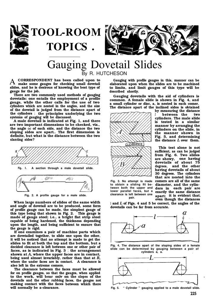
  • common. A female slide is shown in Fig. 4, and

a small cylinder or disc, a, is nested in each comer. The distance apart of the inclined sides is obtained by measuring the distance

1

between the two

  • cylinders. The male slide

is tested in a similar manner by arranging the cylinders on the slide, in the manner shown in

  • Fig. 5, and determining

the distance L over them.

  • Fig. 3. No attempt is made

to obtain a sliding fit be- tween both the upper and lower parallel faces, but a clearance is left between one pair.

This test alone is not sufficient, as can be judged from Fig. 6. Two slides are showy,

  • ne having

dovetails of about 75

degrees,

and the other having dovetails of about 30 degrees. The cylinders that are nested into the comers are all of the same diameter, and the cylin- ders in each pair are exactly the same distance apart; it is evident that. even though the distances

1 and L of Figs. 4 and 5 be correct, the angles of the

dovetails can be far from accurate.

  • Fig. 4. The distance apart of the sloping sides of a female

slide can be determined by gauging between a pair of cylinders a, a.

  • Fig. 5.

“ Cylinder ” gauging applied to a male dovetail slide.

slide-2
SLIDE 2

226

The Model Engineer, March IO, I938 Checking the distance between centres of a pair

  • f

rollers in the above manner must be accompanied by an independent checking of the angles. The angles themselves can be checked by means of profile gauges, and the gauges are best made so that they measure the angle between the flat rubbing face

  • f the slide and the inclined side. Taking the two

slides shown at A in Fig. 3, they can be tested by gauges in the manner depicted by Fig. 7. When

c

J

  • Fig. 6.

Gauging the centre to centre distance of the cylinders is not a sufficient check on the angles.

slides are being machined the first cuts taken should be directed towards obtaining a correct inclination, which can be tested by the gauges of Fig. 7, after which the precise distance apart of the inclined faces can be gauged with the aid of the cylinders. When a dovetail is to be machined, the angle

0~

and depth h are given, and also the full angular width of the slide either at the large or small end

  • f the dovetail, as is indicated by the dimensions
  • Fig. 7. Profile gauges for testing the slope of the sides.

W and w, respectively, in Fig. 8. By “ angular ” width is meant the width if the angles were con- tinued to sharp corners in the manner of Fig. 8. Considering, firstly, the male slide, the distance L

  • ver the cylinders is given by the formula : -

L = d

l+Cotq) + w

If the greater width W were given, instead of the smaller width w, then the smaller width could be readily determined by trigonometry. For a female slide (Fig. 9) the distance I between the cylinders can be determined from the formula:

I= W-d( 1 +Cotq)

The distance L over the rollers of a male slide can be readily measured by means of a micrometer, or a vernier caliper. If the work is being machined to limits, a stepped gap gauge, made of plate, can be employed to check the overall dimension.

  • Figs. 8 and 9. The dimensions to be considered in gauging

dovetail slides.

In the case of the female slide, the distance 2 can be checked by means of the internal jaws of a vernier caliper, or by means of an internal micrometer.

The Largest Diesel-Electric Locomotive in the World

Capable of hauling a loaded l4-car train at a speed of 117 miles per hour, and scheduled to make the trip from Chicago to Los Angeles in

3 9

  • 3

/ 4 hours; the Union Pacific’s newest streamlined

locomotive, “ City of Los Angeles,” with motors, generators, and auxiliary equipment furnished by the General Electric Company of New York, will soon be in regular passenger service. The ,three-unit 5,400 h.p. diesel-electric locomotive that furnishes the motive power for the train is the largest locomotive of this type yet built. It is powered by six 900 h.p. engines, and has six electric generators, which furnish the power to drive the twelve high-speed traction motors on the six three- axle trucks. The traction motors are similar to those in successful use on other high-speed diesel-electric trains. Directly behind the third unit of the locomotive is the auxiliary power car which contains two diesel engines, each of which drives a General Electric 300-kW aiternating-current generator. The two alternators are connected in parallel to supply 600-kW of 60-cycle current to the train line. This current will be used to heat, light, and air condition the train.

slide-3
SLIDE 3

TOOL-ROOM TOPICS Limit-Gauges for Dovetail Slides

By R. HUTCHESON

T

HE last article dealt with the measuring of

ir

dovetail slides, and, more especially, with the cylinder ” method of gauging. To-day, dovetail slides are produced for many small machines in quite large numbers, so that they may be economically made to “ limits,” and limit-gauges of some sort are required in their manufacture, and such gauges may be either profile- or cylinder-gauges. distance of a pair of cylinders for one limit ; the distance B corresponding to the centre-to-centre distance of the cylinders at the other limit. It will be obvious that two separate gauges, each having two plugs, could be used-one for the high and the

  • ther for the low limit, instead of making the centre-

plug of three to serve a dual purpose. Instead of using a gauge of which the plugs are an integral part, gauging may be done as shown in

  • Fig. 3, using separate rollers and a limit-gap gauge,

as shown at a, for testing the male slides, and two end measuring-rods at b whose lengths differ in accordance with the limits allowed on the female-

slide.

I

I

  • _-

L__ __ I I I

I

  • Fig. I.

Limit-gauge with stepped plugs.

  • Fig. 1 shows a limit-gauge embodying measuring-
  • cylinders. The gauge comprises a bar, in which are

set two stepped plugs. The tolerance on the slide is fixed by the designer, and, from one or other of the formula already given, the diameters of the* two steps of the plugs can be readily determined. The forward ends of the plugs are smaller than the rear ends, and, in using the gauge, the slides must be machined to such a size that the two small steps can enter the angles, but the larger steps cannot. When making the above gauge, the formula is utilised to find the diameter of two pairs of cylinders

  • the two sizes of steps-which are the same distance

apart but which will just enter the angles of the slides when at the lower and upper limits; Another form of this gauge employs cylinders of the same diameter, but pitched at different centres, the centres corresponding to the distances pairs of cylinders should be apart to just rest in the angles of slides that are at the lower and upper limits respec-

  • tively. A gauge of this kind is shown in Fig. 2.

Three plugs, all of the same diameter, are set in a

  • bar. The distance A is equal to the centre-to-centre

I i

, I

b------A---+---B------d

Fig: 2 Limit-gauge with differently spaced plugs.

It must be borne in mind that all these tests must be accompanied by .an independent checking of the angles, as has been mentioned previously. Profile-gauges can be adapted for limit-gauging. In

  • Fig. 4, a male slide is shown, and the gauge is

indicated as being in two parts. This gauge enables the angles to be checked, as well as the width of the

slide. In use, the two halves of the gauge are applied

to the work, and the gap between them is tested by

LIMIT GAP GAUGE,

a

END MEASURING ROD,

  • Fig. 3. Gauging with separate rollers (a) checking a male

slide by a limit gap gauge (b) checking a female slide by end measuring rods. means of two feeler-, or slip-gauges, the slide being

within the desired limits, as regards width, when the thin gauge will enter the gap, but the thicker gauge will not. Fig. 5 shows a profile-gauge made in halves in a similar manner, for the testing of a female slide. Instead of making the gauge in two parts and using two feelers, the gauge may consist of three parts. One part is applied to the slide. The other two parts vary in length by an amount corresponding to the tolerance permitted on the work, and the slide is machined to such a size that the smaller part can be 325

slide-4
SLIDE 4

326

1

  • Fig. 4. A profile-gauge in two parts for gauging a male slide.

used in conjunction with the part already on the slide, but the larger part cannot.

Acute-angled Gauges

This is, perhaps, an opportune moment to deal with another query: “ How can a gauge, such as is shown in Fig. 6, be made with a sharp comer to the angle? ” The querist points out that, usually, gauges made of flat plate have holes drilled in the

GAP

  • Fig. 5. A profile-gauge for checking a female slide to limits.

comers (Fig. 7), and these holes afford clearance for

the file or grinding-wheel, and that great di3iculty is

experienced in getting out the sharp comers if it is not desired to drill a hole. If the angle to be worked out is not very acute, the method to adopt is indicated in Fig. 8. A half- round file is employed, and a flat safety side is ground on it, so as to make, with the flat side of the file, a considerably sharper angle than that which it is desired to produce. By using a very fine file,

  • Fig. 6. The type of angle

gauge correspondent de-

sires to make.

  • Fig. 7. The usual form of

angle gauge with clearance hole at corner.

VICE

I

  • Fig. 8. Working out an acute recess with a file specially

ground to shape. almost dead smooth, it will be possible to get right into the sharp comer.

Instead of working out. an acute angle to a sharp comer by direct methods, there is another way of producing the angle. Incidentally, this method is practised considerably by press-tool makers, when they wish to obtain die-openings that would otherwise

The Model Engineer, April 7, 1938

be difficult to work out. This method involves making the-gauge or die in several parts. Suppose, now, we are wishing to make the gauge shown in Fig. 6, the construction shown in Fig. 9 can be employed. The gauge-proper is in two parts, which are held together by a strap, to which they are

secured.

  • Fig. 9. A built-up gauge. I..

_

.

.

,.

. _

  • ._

One piece of plate (Fig. 10) is ground or filed to have two inclined sides, the inclination being 180” minus the gauge-anglein this instance, 180” -30° =

150”. The other plate (Fig. 11) has one dead straight edge filed or ground on it. The two plates are clamped to the strap, so as to butt hard against one another,

and the whole assembly is drilled and tapped to

  • Figs. IO and I I. The two parts of the built-up gauge

that form the sides of the angle.

receive steady-pins and screws, by which the parte are held together. By constructing the gauge in this manner, a sharper corner is obtained in the angle than could be got by filing.

For the Bookshelf

The Engineer’s Sketchbook

by Thomas Walter Barber (London: E. and F. N. Spon,

Ltd.). P&e 10s. &I., postage 5d.

This is the sixth edition of a very unusual, but very useful book. It is, in effect, an illustrated encyclopmdia of mechanical appliances and move- ments of every kind. There are nearly 3,000 illustxa-

tions in diagram and sketch form of engine and

machine details, tools, devices for transmitting power and motion, cranes, lifting appliances, chains, cranks, boilers, gearing, presses, lubricators, locking devices, valve-gea.m, cams and variable motion gears, water- wheels, and a hundred other branches of mechanical interest. A short definition or description accom- panies every illustration. It is a valuable reference- book for designers and inventors, as well as being most instructive from an engineering educational point of view. There are 355 pages packed with mechanical information. .

“,