SLIDE 1
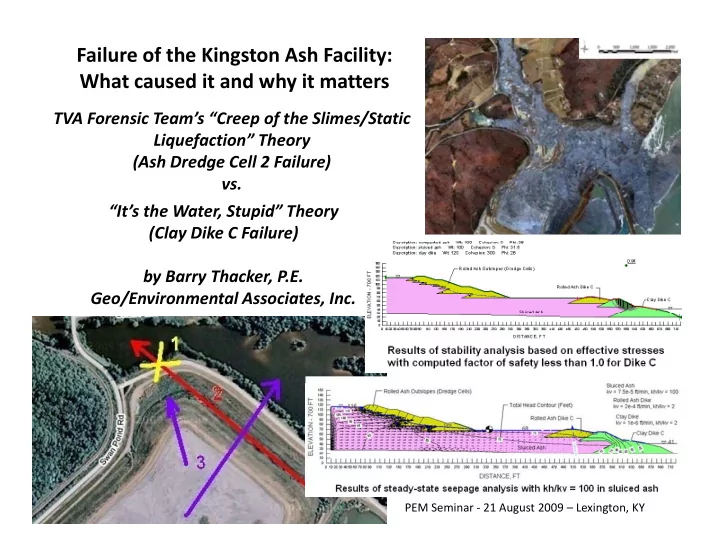
Failure of the Kingston Ash Facility: What caused it and why it matters
TVA Forensic Team’s “Creep of the Slimes/Static Liquefaction” Theory (Ash Dredge Cell 2 Failure) vs. “It’s the Water, Stupid” Theory (Clay Dike C Failure) by Barry Thacker, P.E. Geo/Environmental Associates, Inc.
PEM Seminar ‐ 21 August 2009 – Lexington, KY
SLIDE 2 The failure occurred around 1:00 a.m. EST, on Monday, December 22, 2008, when the north and
KINGSTON ASH FACILITY FAILURE
(Background Information from Forensic Report)
central portions of Cell 2 at the Kingston Fossil Plant ash disposal site suddenly failed. An estimated 5.4 million cubic yards estimated 5.4 million cubic yards
- f material, consisting primarily
- f hydraulic‐filled ash and
intermediate stage containment dik l d i dikes, were released in a progressive sequence of flow slides over a period of approximately one hour. pp y Ultimately, the flow slide would extend northward approximately 3,200 feet beyond the limits of , y the original ash pond over the Swan Pond Creek flood plain, a back water slough of the Emory River and into the former Emory River and into the former Emory River Channel of Watts Bar Reservoir.
SLIDE 3 Missed c Missed clue #1?... ue #1?... Ho How could w could ash tr ash travel el near nearly 2/3 of 2/3 of a mile a mile
N
TVA’S FORENSIC TEAM: First‐time in history phenomenon, denoted as “Creep of the Slimes/Static
to the to the nor northw thw est fr st from f
ilure e
a dr dredge cell outslope w ith edge cell outslope w ith a nor a northeaster theastern orienta
ion?
Creep of the Slimes/Static Liquefaction”, is modeled using undrained shear strength for a buried slimes layer and the overlying sluiced
Hint: Dike C had a northwestern‐ facing limb
ash, and predicts failure of the dredge cells. Dike C Dredge Cells
SLIDE 4 OPINION BY AECOM AS TO CAUSE OF THE KINGSTON ASH FACILITY FAILURE (From Forensic Report): The north end of Dredge Cell 2 was on the verge of failure due to the high stresses and creep in the loose wet layer of weak slimes. The deformation of the slimes in turn caused p y the overlying collapsible wet ash to liquefy. Failure of the Kingston dredge cells was sudden and complex in nature due its geographic setting and being built within the Watts Bar Reservoir after the lake was formed. It took a forensic type study to determine the propensity
- f the ash to liquefy at low strain levels when the material cannot drain and thus becomes
- f the ash to liquefy at low strain levels when the material cannot drain and thus becomes
undrained, and to locate the slide plane in the unusual, creep susceptible, low undrained shear strength slime layer that underlies Cell 2. In AECOM’s opinion, subsurface conditions at the dredge cells were unusual and rarely found. The consequence of failure in the slimes led to the collapse of the dredge cell and loss of the saturated contents of the ash landfill due to the breach of perimeter Dike C. (NOTE: AECOM’s primary failure (NOTE: AECOM s primary failure surface was analyzed at the location of a former knob, whereas the thickness
- f ash is greater beneath Dike C’s
th t li b ) northwestern limb.)
Dike C
SLIDE 5
Initial Burst Location of Dike C (Based on “It’s the Water, Stupid” A l i ) Analysis) Initial Static Liquefaction Location of Dredge Cells (Based on TVA’s Forensic
AECOM RELIC SURVEY
Dredge Cells (Based on TVA s Forensic Team )
SURVEY DATA
SLIDE 6
CORROBORATING RESULTS OF ENGINEERING ANALYSIS USING FORENSIC EVIDENCE:
My buddy, Ray Bob, offered some of his observations about the forensic study. He is proud to describe himself as, “a snuff‐dippin’, coal‐minin’, 6‐foot‐6, 250‐pound, American Veteran”; and his friends call him “Tiny”. Tiny brought to my attention the Expected Failure Mode slide from the forensic study shown below that he says “Must be one of them cartoons they make in the forensic study shown below that he says, Must be one of them cartoons they make in Hollywood.”
Tiny says to look real close at how real close at how the ash from the “dredge sales” supposedly pp y “lickerfide” and ran over Dike C.
SLIDE 7 Tiny gave me two Dike C figures/photos from the AECOM forensic report, which are shown at
- right. According to Tiny, “Do ya
seed whar I drawt ‘SEE‐DIK (THEN)’ and ‘SEE‐DIK (NOW)’? “ “If that‐there Hollywood cartoon from them forensic fellers was true, then the grass on top of the See‐Dik slope they say got flooded and pushed they say got flooded and pushed seven‐hundurd feet to the northeast by the tidal wave of lickerfide ash from failurt of the dredge sales would at least be tarnished and flat, and not as fresh as a Daisy Duke.” “At least in the Road Runner and Wile
- E. Coyote cartoons, they showt the
coyote with matted fur, and seaweed stuck in his ear, after he gets hammered by the tidal wave ” hammered by the tidal wave.”
SLIDE 8
Tiny gave me two photos of the relic cattails from the AECOM report as shown below, and informed me that you can’t push a rope, you have to pull a rope to get it to move. In his words, “Do ya seed whar I drawt ‘CATTAILS (THEN)’ and ‘CATTAILS (NOW)’? Thur is no way on God’s Green Earth them dredge sales could push a clump of cattails two‐thirds of a mile up the holler to the northwest without destroyin’ them. Do them forensic fellers expect us to believe that the dredge sales had the force to push See‐Dik seven‐hundurd feet to the northeast, yet not hurt a hair on the fur of a cattail’s haid? Yea rite! The only way them cattails could “Don’t them forensic fellers knows that a cattail is as fragile as… ummmmm, a cattail”? not hurt a hair on the fur of a cattail s haid?... Yea, rite! The only way them cattails could have moved that furr a piece up the holler to the northwest is by ridin’ on the back of the sluiced ash after the northwestern limb of See‐Dik burst.” Don t them forensic fellers knows that a cattail is as fragile as… ummmmm, a cattail ?
SLIDE 9
Relics from Dredge Cell 2 Outfall Pipe Found Northeast of Original Location – illustrating that the dredge cells failed last after the bursting of Dike C undermined after the bursting of Dike C undermined the northeastern outslope of Dredge Cell 2
N Initial burst location of Dike C
Cell 2 Outfall Pipe (Original Location) Location) Dredge Cell 2
SLIDE 10
OPINION BY BARRY THACKER, P.E.: Dike C burst at its northwestern limb due to artesian pore water pressures p p in the underlying sluiced ash; then it was like Dominoes, the game, not the pizza.
SLIDE 11
Piezometer locations and water level data provided by TVA/AECOM: For reference purposes, the ground surface at MW‐15 is at elevation 771 feet; thus, water levels in MW‐15 above elevation 771 feet represent artesian conditions in the sluiced ash. Trend in water levels in i f l 11/19/08 lid Th k d l piezometers after last measurement on 11/19/08 validates Thacker seepage model.
Note: The alluvium beneath Dike C where MW‐4B was screened was not included in the Thacker model.
SLIDE 12
LET’S NOW EXAMINE THE DETAILS: Missed Clue #2? Mitigation report prepared after a 2003 incident at the northwestern toe of the dredge cells concludes that a “blowout” was caused by “excessive seepage and piping”, yet y p g p p g , y internal drains were proposed to increase the rate of seepage – Is that logical?
2003 “Blowout” at toe of Northwestern Outslope of Dredge Cells Hint: Hinge No 1 Hint: Hinge No. 1
Hint: Bottom Ash Lenses
SLIDE 13 In reviewing the input data used in the AECOM seepage modeling, I see that AECOM used a ratio of horizontal hydraulic conductivity (kh) to vertical hydraulic conductivity (kv) = 1. Maybe, the engineers at AECOM do not realize the impact the black, more pervious bottom ash lenses, shown in the photo at left from the AECOM report, have on the kh/kv ratio; or how a high kh/kv ratio can in some circumstances cause significant uplift pore water can in some circumstances cause significant uplift pore water pressure in sluiced ash, hydraulic fill.
Hinge (i.e. thin, potentially weak zone subject to failure by high pore water seepage pressures)
I learned that lesson decades ago from a gray‐haired engineer with the U.S. Mine Safety and Health Administration (MSHA) who referred
Note: kh/kv = 100
Administration (MSHA) who referred me to the results of the forensic study
- f the 1972 Buffalo Creek Slurry
Impoundment failure, shown at right. One of the early practitioners in design of ash disposal facilities was Professor Arthur Casagrande of Harvard University. A 1971 design report he co‐authored states: “When fly ash is deposited from a slurry in a pond, considerable segregation develops according to grain size p f y p g g p g g and specific gravity. The resulting stratification and loose structure produces relatively high horizontal permeability.“ I have found that kh/kv can vary from 1 to 100 at the same site, so I believe use of kh/kv = 100 for hydraulic fill in seepage analysis is prudent.
SLIDE 14 Sluiced ash is not a homogeneous deposit. When fly ash and bottom ash are co‐mingled during hydraulic filling, the resulting deposit can contain a gazillion lenses of bottom ash surrounded by fly ash. From TVA‐00013627 (Northwestern
dredge cells)
Outer Dike kv = 2e-4 ft/min, kh/kv = 2 Fly Ash kv = 7.5e-5 ft/min, kh/kv = 10 Base Material Outer Dike UPLIFT PRESSURE IN FLY ASH DUE TO HIGH Kh/Kv RATIO
Hydraulic fill should be modeled in seepage analysis using high kh/kv ratios where kh is the hydraulic conductivity
Clay Dike Fly Ash Kh/Kv RATIO
60 65 70 75
g y y in the horizontal direction and kv is the hydraulic conductivity in the vertical direction. Doing so, yields a prediction of artesian pressures at toe as shown at right.
SLIDE 15 My independent assessment based on steady‐state seepage and stability analysis using effective stresses shows that the northwestern outslope of the dredge cells is unstable at kh/kv = 50 with only the shallow surface drains installed after the 2003 “blowout”.
Outer Dike Base Material kv = 3.4e-5 ft/min, kh/kv = 2
/ y
Outer Dike kv = 2e-4 ft/min, kh/kv = 2 Fly Ash kv = 7.5e-5 ft/min, kh/kv = 50
High kh/kv levels in the sluiced ash would explain why a new “blowout” was reported in 2006
Description: outer dike Wt: 95 Cohesion: 0 Phi: 36 Description: fly ash Wt: 105 Cohesion: 0 Phi: 31.5 Description: clay dike Wt: 110 Cohesion: 0 Phi: 30 Description: base material Wt: 95 Cohesion: 0 Phi: 36 Description: rockfill Wt: 95 Cohesion: 0 Phi: 36
150 160 170
blowout was reported in 2006 after the sluiced ash level raised.
0.9 3
Outer Dike
N - 700 FT
100 110 120 130 140 150
Base Material Clay Dike Fly Ash
ELEVATION
50 60 70 80 90
DISTANCE, FT
10 20 30 40 50 60 70 80 90 100 110 120 130 140 150 160 170 180 190 200 210 220 230 240 250 260 270 280 290 300 310 320 330 340 350 360 370 380 390 400 20 30 40
SLIDE 16 (for northwest outslope of dredge cells adjacent to Swan Pond Road) (Documenting inspection from October 2008)
My independent assessment shows that the northwestern
- utslope of the dredge cells is
stable with adequate relief wells even at kh/kv = 100
Bottom ash lenses
SLIDE 17 Independent analysis of northeastern outslope of dredge cells based on steady‐
Rolled Ash Dike Clay Dike kv = 1e-6 ft/min, kh/kv = 2 Name: k100failure dredge overall.gsz
p y p g y state seepage and effective stresses for kh/kv = 100 in sluiced ash:
My independent assessment shows that
1.84 Description: compacted ash Wt: 100 Cohesion: 0 Phi: 36 Description: sluiced ash Wt: 100 Cohesion: 0 Phi: 31.5 Description: clay dike Wt: 120 Cohesion: 300 Phi: 26 Rolled Ash Dike kv = 2e-4 ft/min, kh/kv = 2 Sluiced Ash kv = 7.5e-5 ft/min, kh/kv = 100
150
Hinge No 2
the northeastern
cells is stable as designed even at kh/kv = 100, in
8 Rolled Ash Outslopes (Dredge Cells) Clay Dike C Rolled Ash Dike C
TION - 700 FT
60 70 80 90 100 110 120 130 140 150
Hinge No. 2
/ , spite of the presence of Hinge No. 2.
y Sluiced Ash
DISTANCE, FT
0 10 20 30 40 50 60 70 80 90 110 130 150 170 190 210 230 250 270 290 310 330 350 370 390 410 430 450 470 490 510 530 550 570 590 610 630 650 670 690 710
ELEVAT
10 20 30 40 50
SLIDE 18 Analysis of Dike C with saturated sluiced ash between Dike C and the northeastern outslope of the dredge cells:
Dike C has no internal drains, so how does seepage drain
Description: rolled ash Wt: 100 Cohesion: 0 Phi: 36 Description: sluiced ash Wt: 100 Cohesion: 0 Phi: 31.5 Name: k100predredge stability upper.gsz
from Dike C? (Not in a controlled manner, which can result in high pore water pressure as shown above).
Sluiced Ash kv = 7.5e-5 ft/min, kh/kv = 100 Rolled Ash Dike kv = 2e-4 ft/min, kh/kv = 2 Clay Dike kv = 1e-6 ft/min, kh/kv = 2 Description: clay dike Wt: 120 Cohesion: 300 Phi: 26
150
1.61
Clay Dike C Rolled Ash Dike C 68 41
VATION - 700 FT
50 60 70 80 90 100 110 120 130 140 150
Hinge No. 3
Sluiced Ash 41
D ISTAN C E , FT
0 10 2030 40 50 6070 80 90 110 130 150 170 190 210 230 250 270 290 310 330 350 370 390 410 430 450 470 490 510 530 550 570 590 610 630 650 670 690 710
ELEV
10 20 30 40
‐ Pre‐dredge cell condition with minimum factor of safety greater than 1.5 ‐ Pre dredge cell condition with minimum factor of safety greater than 1.5
NOTE: Knowing how TVA overbuilds, I modeled the clay fill of Dike C with an apparent cohesion of 300 psf due to compaction.
SLIDE 19 Rolled Ash Dike kv = 2e-4 ft/min kh/kv = 2 Clay Dike kv =1e-6 ft/min, kh/kv = 2 Name: k100 previous dike c mid.gsz
When sluiced ash Independent analysis reveals:
1.04 Rolled Ash Outslopes (Dredge Cells) Sluiced Ash kv = 7.5e-5 ft/min, kh/kv = 100 kv 2e 4 ft/min, kh/kv 2 Description: compacted ash Wt: 100 Cohesion: 0 Phi: 36 Description: sluiced ash Wt: 100 Cohesion: 0 Phi: 31.5 Description: clay dike Wt: 120 Cohesion: 300 Phi: 26
00 FT
110 120 130 140 150
‐ When sluiced ash in dredge cells is at
minimum factor of
Clay Dike C Sluiced Ash Rolled Ash Dike C
0 10 20 30 40 50 60 70 80 90 110 130 150 170 190 210 230 250 270 290 310 330 350 370 390 410 430 450 470 490 510 530 550 570 590 610 630 650 670 690 710
ELEVATION - 70
10 20 30 40 50 60 70 80 90 100
Bottom ash lenses
safety for Dike C is
greater than 1.0 ‐
DISTANCE, FT Description: compacted ash Wt: 100 Cohesion: 0 Phi: 36 Description: sluiced ash Wt: 100 Cohesion: 0 Phi: 31.5 Rolled Ash Dike kv = 2e-4 ft/min, kh/kv = 2 Sluiced Ash k 7 5 5 ft/ i kh/k 100 Clay Dike kv = 1e-6 ft/min, kh/kv = 2 Name: k100failure dike c mid.gsz
‐ Condition on 22 D b 2008 ith
0.96 Rolled Ash Outslopes (Dredge Cells) Description: clay dike Wt: 120 Cohesion: 300 Phi: 26 kv = 7.5e-5 ft/min, kh/kv = 100 Rolled Ash Dike C
90 100 110 120 130 140 150
December 2008 with sluiced ash in dredge cells at El. 816 feet ‐
Clay Dike C Sluiced Ash Rolled Ash Dike C
0 10 20 30 40 50 60 70 80 90 110 130 150 170 190 210 230 250 270 290 310 330 350 370 390 410 430 450 470 490 510 530 550 570 590 610 630 650 670 690 710
ELEVATION -
10 20 30 40 50 60 70 80 90
DISTANCE, FT
Voilà, steady‐state seepage and stability analysis based on effective stresses predicts failure
- f Dike C with computed F.S. less than 1.0 on 22 December 2008 as shown above.
SLIDE 20
For an imaginary piezometer (MW‐4C) installed through the clay‐portion of Dike C at the elevation 765 bench, and screened in the sluiced ash at elevation 740 feet (shown above), modeling predicts water levels for kh/kv = 1 10 and 100 in the sluiced ash as shown below: modeling predicts water levels for kh/kv = 1, 10, and 100 in the sluiced ash as shown below:
When Dike C burst as a result of these high pore water seepage it th lik pressures, it was then like Dominoes (the game, not the pizza)!
SLIDE 21
In summary:
Note: Ash could have travelled two‐thirds of a mile to the northwest without help from “Left‐ T L ” (K ill lit ) l if Turn Laverne” (Knoxville personality) only if that was the direction sluiced ash exploded from the initial rupture of Dike C.
SLIDE 22 Conclusion: High pore water seepage pressure resulted in t i diti ithi Tiny’s additional sketches: an artesian condition within the sluiced ash beneath the clay‐portion of Dike C, which was the driving force behind the failure. Dike C ruptured at its most vulnerable location where it crossed the
- riginal Swan Pond Creek
- riginal Swan Pond Creek.
Excavation of the diversion channel by TVA to allow construction of Dike C in the 1950s may have provided drainage along much of its length for natural sand lenses within the alluvium however, no such drainage of natural sand lenses was provided beneath the northwestern lenses within the alluvium that forms the bottom of the ash disposal facility; limb of Dike C. Regardless, failure was inevitable because the increasing sluiced ash level of the dredge cells would have resulted in increased pore water pressure beneath Dike C due to Dike C’s lack of internal drainage provisions.
SLIDE 23 Why the cause of failure at Kingston matters to PEM:
I am relieved that the method we use in design and performance monitoring of mining‐ related hydraulic fill structures (i.e. seepage/stability modeling according to effective stresses with confirmation monitoring of pore water pressures using piezometers) appears
- prudent. Based on my analysis, if that method had been used at Kingston, then mitigation
measures could have been taken to avert the failure; however, if that method is wrong, I want to know now Who is right doesn’t matter; what is right counts
Why I am convinced Dike C burst due to artesian pore water pressures:
When I suspected in February 2009 that failure at Kingston was probably caused by artesian pore water pressures in the sluiced ash one of my utility clients said “We may have similar want to know now. Who is right doesn t matter; what is right counts. pore water pressures in the sluiced ash, one of my utility clients said, We may have similar symptoms at the toe of one of our dredge cells.” Piezometers were installed, revealing as much as 4 feet of artesian head at the toe of the dredge cells. Internal drainage and buttress improvements were made along 5,000 linear feet
- f dredge cell toe by May 2009; thus, the theory in my June 2009 white paper report assessing
that artesian pore water pressures caused the failure of Kingston’s Dike C had been validated and remediated at another ash disposal site. In defense of TVA, I found no evidence faulting it for actions taken during design and construction of the dredge cells. Results of my analysis show the dredge cells were safe until undermining of their foundation by failure of Dike C. Failing to recognize that the dredge cells caused increased pore water pressures beneath Dike C is a regrettable, yet understandable, caused increased pore water pressures beneath Dike C is a regrettable, yet understandable, mistake that can only be corrected on other sites if the actual cause of failure at Kingston is recognized.... Also, if forensic experts couldn’t figure it out after the failure, then how can TVA be criticized for not recognizing the potential problem at Dike C before the failure?
SLIDE 24 Lessons‐Learned:
- When humans first built walls, water accumulated behind some and they failed.
- Our ancestors didn’t adopt undrained “Creep of the Slimes/Static Liquefaction” theory and
- In my opinion, the Kingston failure validates current, prudent engineering practice for the
Our ancestors didn t adopt undrained Creep of the Slimes/Static Liquefaction theory and design/build stronger walls, they put drains behind the walls to reduce the potential for water to accumulate. design of hydraulic fill structures such as slurry impoundments … and reinforces my fear of hinges and respect for water.
- What we should learn from the Kingston failure is that if Dike C had been raised with
t d h d i t l d i i il t th t ti f th th t t l compacted ash and internal drains, similar to the construction of the northeastern outslope
- f the dredge cells, then failure of the Kingston Ash Facility would likely have been averted;
but, monitor pore water pressures beneath hinges 2 p g and 3, because pore water pressures here could increase as sluiced ash levels increase
SLIDE 25 Lessons‐Learned (continued):
- What we should also learn from the Kingston failure is that if shallow trench drains and relief
wells had been installed at Dike C as mitigation similar to those installed at the northwestern wells had been installed at Dike C as mitigation, similar to those installed at the northwestern
- utslope of the dredge cells after the 2006 “blowout”, then failure of the Kingston Ash Facility
would likely have been averted;
but, monitor pore water pressures beneath hinges 2 and 3, because pore water pressures here could l d h l l increase as sluiced ash levels increase
However, merely building the dredge cells on a flatter outslope to resist an undrained “Creep of the Slimes/Static Liquefaction” failure would have made no difference in the outcome… because, as the sign on my office wall says, “It’s the water, Stupid”
SLIDE 26
Despite heavy rains for two weeks prior to this field trip to plant American chestnuts … and speaking of water, kudos to OSM and state agencies for recognizing and promoting the merits of the Forestry Reclamation Approach… Despite heavy rains for two weeks prior to this field trip to plant American chestnuts, water had already soaked into the loose, rocky spoil at this FRA site to irrigate tree roots as evidenced by the fact that none of the students got muddy... Observing a “shot” being put off Neither did this sedimentation pond sedimentation pond