
SLIDE 1
F lexible-wing MAVs F lexible-wing MAVs
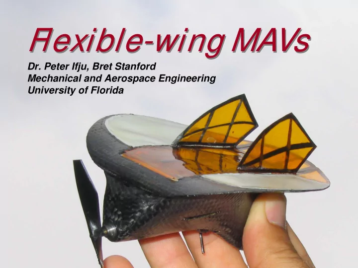
- Dr. Peter Ifju, Bret Stanford
Mechanical and Aerospace Engineering University of Florida
F lexible-wing MAVs F lexible-wing MAVs Dr. Peter Ifju, Bret - - PowerPoint PPT Presentation
F lexible-wing MAVs F lexible-wing MAVs Dr. Peter Ifju, Bret Stanford Mechanical and Aerospace Engineering University of Florida Special Thanks Special Thanks Students: James Davis Yongsheng Lian Bret Stanford Thomas Rambo Roberto
Mechanical and Aerospace Engineering University of Florida
Students:
Bret Stanford Roberto Albertani Kyu-Ho Lee Sewoong Jung Scott Ettinger Mujahid Abdulrahim Don McArthur Dan Claxton Frank Boria Mike Sytsma Jos Coquyt Dragos Viieru Baron Johnson Mike Morton James Clifton Scott Bowman
UF Faculty:
Rick Lind Warren Dixon Paul Hubner Wei Shyy Rafi Haftka David Jenkins Andy Kurdila Carl Crane Warren Dixon Franklin Percival Mike Nechyba
Sponsors:
Air Force Office of Scientific Research AFRL at Eglin Air Force Base US Special Operations Command NASA Langley Research Center US Geological Survey US Dept of Fisheries and Wildlife James Davis Yongsheng Lian Thomas Rambo Albert Lin Brandon Evers
Undercambered wing provides better aerodynamic characteristics at Reynolds No. below 100,000. Flexibility can be tuned for smoother flight in gusty wind conditions “adaptive washout”. We have built wings with improved longitudinal stability. Delayed/gentle stall has been documented Flexible wing can be morphed efficiently. Flexible wings can be folded for storage and deployed without assembly. Wing configuration can be engineered to be lightweight as well as durable
Morphing Morphing Gust Alleviation Gust Alleviation Storage Storage Durability Durability Stability, high lift Stability, high lift
geometry
planform shape
MAVLab: rapid wing generation
Finished tool with layout pattern Prepreg unidirectional, woven carbon fiber and Kevlar composite construction
Vacuum bagging Fuselage layup Component installation Assembly
material is applied
1997 1998 1999 2000 2001 2002 2003 2004 2005 2006 10 25 50 MLB MLB UF UF UF UF UF UF BYU KKU UF 4.5 in. (11.4 cm) record
Maximum Dimension, cm
15
Smallest MAV to identify target at 600m
Year
[±453] [±452] Latex Skin [02]
Rigid Batten-Reinforced BR Perimeter-Reinforced PR
composites, and latex rubber skin
– AR = 1.25, root chord = 130 mm, wing span = 150 mm
The other wings before stall
substantially higher than the rigid case with the batten reinforced wing intermediate
cameras (35 mm lens, 1.3 mega pixels, 5-10 ms exposure times) each looking at a different angle
geometry in question, the VIC system digitally acquires the pattern, and tracks the deformation of each speckle
Synchronized cameras Wind tunnel Model 250 Watt lamp
12° AOA, Wind Speed = 13 m/s
Wing fixed here: Non-zero displacement implies a small rigid body rotation of entire model Primary region of deformation: battens are forced to bend upwards due to wind loading Deformation patterns here imply that the wind load subjects the leading edge to torsion
12° AOA, Wind Speed = 13 m/s
Wing fixed here: Non-zero displacement implies a small rigid body rotation of entire model The primary region of deformation occurs as the membrane billows upwards due to the aerodynamic forces The carbon fiber perimeter exhibits substantial bending
complicated fluid-structure interaction over a flexible MAV
elements are used: shells to model the carbon fiber weave (red), beams to model the battens (green), and membranes to model the latex skin (blue)
the wing, and comparing numerical and experimental displacement fields Out-of-plane displacements caused by a 7 g load at the tip of the outer left batten (MAV clamped at trailing edge) Experimental (VIC) Numerical (FEA)
High fidelity finite element analysis (FEA) structural model With nonlinear membrane properties Navier Stokes based computational fluid dynamics (CFD) model with master/slave perturbation techniques for remeshing Define rigid wing geometry Conduct CFD on rigid wing Apply aero loads from CFD to FEA Deformed shape analyzed by CFD Apply new aero loads to FEA
Stop when wing geometry converges
Out-of-plane displacement Chord-wise strain
Span-wise strain Shear strain
Out-of-plane displacement Chord-wise strain
Span-wise strain Shear strain
0AOA, top 0AOA, bottom
Rigid Batten Perimeter Rigid Batten Perimeter
15AOA, top
Rigid Batten Perimeter Rigid Batten Perimeter 15AOA, bottom
some flight parameters with both the batten reinforced and perimeter reinforced membrane wing
high fidelity information that can give insight into the mechanisms that lead to enhanced flight performance
improve specific flight characteristics
better ways to reinforce the wing for specific objective functions
experimentally characterizing the flow field is desired.