
SLIDE 1
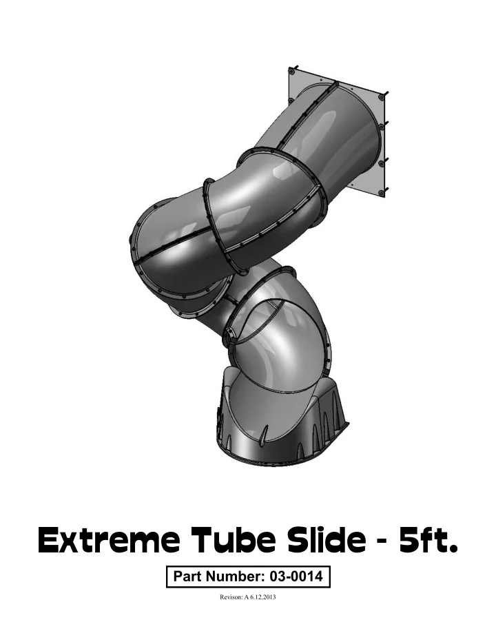
Extreme Tube Slide - 5ft.
Part Number: 03-0014
Revison: A 6.12.2013
Extreme Tube Slide - 5ft. Part Number: 03-0014 Revison: A 6.12.2013 - - PDF document
Extreme Tube Slide - 5ft. Part Number: 03-0014 Revison: A 6.12.2013 Please inspect and inventory all parts immediately upon accepting delivery. Use the in- ventory pages in the manual to make sure you have received all necessary parts. The
Part Number: 03-0014
Revison: A 6.12.2013
Please inspect and inventory all parts immediately upon accepting delivery. Use the in- ventory pages in the manual to make sure you have received all necessary parts. The quickest method to get any parts that are missing or damaged is to contact the seller.
PLEASE RETAIN ALL INSTRUCTIONS FOR FUTURE REFERENCE. KEEP THEM IN A SAFE PLACE WHERE YOU CAN REFER TO THEM AS NEEDED. CHECK FOR REVISED INSTRUC- TIONS WITH THE SELLER SHOULD THE INSTRUCTIONS NOT MATCH THE SLIDE PROPERLY.
IMPORTANT SAFETY GUIDELINES
This product is recommended for use by children ages 3-11. This product is intended for residential use only and not intended for use in any public setting. A safety surface such as mulch or recycled tire should be used around the slide to prevent injury from falls. Also a 6 foot safety zone should be used around the entire slide. As with any home project, good judgment and respect for power tools will greatly reduce the risk
protection and safety gloves to prevent injury. In several phases of construction two people may be required for lifting and securing of parts. While the slide is being constructed/attached, please keep children off the equipment until the project is complete. Bolts and screw heads should be checked regularly for tightness. The seller and/or manufacturer shall not be liable for incidental, indirect or consequential damages
anytime the slide is being used.
WEIGHT LIMIT: 150 LBS.
We recommend that the weight limit must not be exceeded. Failure to adhere to these and other safety guidelines could result in damage to the slide and injury to the users. 2
Safety and Maintenance Tips:
NOTE: Your children’s safety is our #1 concern. Observing the following statements and warnings reduces the likelihood of serious
children.
clothing such as scarves and ponchos should not be worn. Always take off, tie up or tuck in cords and drawstrings on children’s clothing. These things can get caught on playground equipment and strangle a child.
designed for use with the equipment, such as, but not limited to, jump ropes, clothesline, pet leashes, cables and chain as they may cause a strangulation hazard.
WARNING: Children must NOT use this slide until it has been completely assembled and inspected by an adult to insure it has been properly installed.
Playgrounds should be inspected on a regular basis. If any of the following conditions are noted, they should be removed, corrected, or repaired immediately to prevent injuries.
(But not so tight that you crack the wood) It is particularly important that this procedure be followed at the beginning of each season.
they are in place. Replace when necessary. It is especially important to do this at the beginning
depths.
disposed of in such away that no unreasonable hazards will exist at the time the unit is discarded.
3
Play Set Surfacing Recommendations:
Below are some of the recommendations that the U.S. Consumer Product Safety Commission (CPSC) offers from its Handbook for Public Playground Safety. The guide can be downloaded in full at www.cpsc.gov/cpscpub/pubs/325.pdf
ground, protective surfacing under and around all playground equipment is the most critical safety factor on playgrounds. Certain manufactured synthetic surfaces also are acceptable; however, test data on shock absorbing performance should be requested from the manufacturer. Asphalt and concrete are unacceptable. They do not have any shock absorbing
during a fall can be reduced considerably through wear and environmental conditions. Certain loose-fjll surfacing materials are acceptable. Surfacing materials are acceptable, such as the types and depths shown in the table.
Fall Heights and Materials
Type Of Material 6 in. depth 9 in. depth 12 in. depth Double-Shredded bark mulch 6’ Fall Height 10’ Fall Height 11’ Fall Height Wood Chips 6’ Fall Height 7’ Fall Height 12’ Fall Height Fine Sand 5’ Fall Height 5’ Fall Height 9’ Fall Height Shredded Tires* 10-12’ Fall Height N/A N/A Fine Gravel 6’ Fall Height 7’ Fall Height 10’ Fall Height
*This data is from tests conducted by independent testing laboratories on a 6-inch depth of uncompressed shredded tire samples produced by four manufacturers. The tests reported critical heights, which varied from 10 feet to greater than 12 feet. It is recommended that persons seeking to install shredded tires as a protective surface request test data from the supplier showing the critical height of the material when it was tested in accordance with ASTM F1292.
It should be recognized that all injuries due to falls cannot be prevented no matter what surfacing material is used.
under and around equipment where a child might fall. This area should be free of other equipment and obstacles onto which a child might fall. Stationary climbing equipment and slides should have a fall zone extending a Minimum of 6’ in all directions from the perimeter of the equipment. 4
General Info to Review Before Installation
up to 2 hours, after inventory of parts; therefore, we recommend you set aside at least 2 hours for assembly.
see them. Your instruction book will have detailed drawings that will make it easy for you to recognize individual parts.
there are no broken pieces.
so that you do not lose any pieces in the grass. This will save time and familiarize you with all the different pieces in the hardware bag.
Reading instructions after you have studied the parts will help you understand the installation process, and help to eliminate unnecessary mistakes.
alignment while you are attaching parts together. After everything is square, tighten each joint.
slide is secured to the play set.
seasonally.
such as a fence, garage, house, overhanging branches, laundry lines, or electrical wires.
REQUIRED TOOL LIST:
___ Standard or Cordless Drill ___ Drill Bit, 11/64” to predrill holes for lag screws. ___ ½” Wrench and Socket ___ ½” Deep Well Socket ___ 9/16” Deep Well Socket ___ 9/16” Wrench and Socket ___ Tape Measure ___ Extension Cord (if using standard drill) ___ Pencil ___ Shovel 5
59" 52" 31" 29"
Note: 59” dimension is the deck height when the
fmush to the deck. Slide is shown on a tower which is approximately 3ft x 3ft square. Typically the tower depicted is at- tached to a larger Fort structure for stability. The slide must be attached to a “freestanding fort structure” no less than 4ft x 4ft square and no greater than 8ft in height. Also this “freestanding fort structure” shall have anchors resembling hur- ricane stakes attached to the corner posts. The anchors must be buried in the ground no less than 18 inches.
6
5/ 16 X 3/ 4" HEX BO LT Q T Y: 110 5/ 16 X 1" HEX BO LT Q T Y: 4
9 1 4 3 2 5 6 7 8 USE T HE RULER T O T HE RI G HT T O MEASURE YO UR BO LT S AND SC REWS. PI C T URE VI EWS SHO WN ABO VE ARE 1:1 SC ALE AND C AN BE USED T O MAT C H BO LT AND SC REW SI ZES.
LAG SC REW Q T Y: 12 Q T Y: 114 5/ 16" LO C K NUT Q T Y: 228 5/ 16" WASHER 3/ 8 x 3-1/ 2" 3/ 8 X 1-3/ 4" WASHER Q T Y: 12
11-2024 EXT REME T UBE SLI DE HARDWARE REV:A 1/ 17/ 2013
7
B A2 A1
PI C T URE DESC RI PT I O N Q T Y. SEC T I O NS A1=LEFT BEND AND
A2= RI G HT
ENT RY ELBO W SEC T I O N 60
REI NFO RC EMENT PLAT E
8
C D
"D" MARKI NG I S UNDERNEAT H SLI DE I N T HE C ENT ER AREA DENO T ED.
FO O T
1
EXI T SEC T I O N 60 BEND
1
PI C T URE DESC RI PT I O N Q T Y. 9
ST EP 1: T HE LEFT AND RIG HT ENT RANC E SEC T IO N
E T HE LEFT AND RIG HT ENT RANC E SEC T IO NS.
EN T HE LEFT AND RIG HT SEC T IO NS T O G ET HER ALO NG T HE T O P RIB WIT H 5/ 16 X 3/ 4" HEX BO LT S, 5/ 16" WASHERS, AND 5/ 16" LO C K NUT S. 5/ 16 X 3/ 4" 5/ 16" WASHER HEX BO LT LEFT AND RIG HT SLIDE ENT RANC E SEC T IO NS 5/ 16" LO C K NUT
10
ST EP 2: REINFO RC EMENT PLAT E
EN T HE REINFO RC EMENT PLAT E UNDERNEAT H T HE ENT RANC E SEC T IO NS WIT H 5/ 16 X 1" HEX BO LT S, 5/ 16" WASHERS, AND 5/ 16" LO C K NUT S.
5/ 16" LO C K NUT 5/ 16" WASHER 5/ 16 X 1" HEX BO LT LEFT AND RIG HT SLIDE ENT RANC E SEC T IO NS REINFO RC EMENT PLAT E
11
ST EP 3: ASSEMBLING T HE SLIDE SEC T IO NS
E T WO 60 SLIDE SEC T IO NS. FAST EN T HE T WO PIEC ES T O G ET HER ALO NG T HE RIBS WIT H 5/ 16 X 3/ 4" HEX BO LT S, 5/ 16" WASHERS, AND 5/ 16" LO C K NUT
T HREE MO RE T IMES.
H T HE REMAINING 60 SLIDE SEC T IO N AND T HE 60 EXIT SEC T IO N, YO U WILL ASSEMBLE T HE SLIDE EXIT . T HE SLIDE EXIT IS ASSEMBLED T HE SAME WAY T HAT T HE O T HER 60 SEC T IO N WAS ASSEMBLED. HEX BO LT 5/ 16 X 3/ 4" 5/ 16" LO C K NUT 5/ 16" WASHER SLIDE SEC T IO N C O MPLET ED ELBO W HEX BO LT SLIDE EXIT 5/ 16" WASHER 5/ 16 X 3/ 4" 5/ 16" LO C K NUT
12
ST EP 4: AT T AC H ELBO W T O T HE SLIDE ENT RY ASSEMBLY
T AC H AN ELBO W T O T HE SLIDE ENT RY ASSEMBLY WIT H 5/ 16 X 3/ 4" HEX BO LT S, 5/ 16" WASHERS, AND 5/ 16" LO C K NUT
O RO T AT E T HE ELBO W T WO HO LES DO WN AS SHO WN BELO W. SLIDE ENT RY ASSEMBLY 5/ 16" WASHER ELBO W 5/ 16 X 3/ 4" HEX BO LT RO T AT E HO LES 5/ 16" LO C K NUT
13
5/ 16" LO C K NUT HEX BO LT 5/ 16" WASHER 5/ 16 X 3/ 4" ELBO W
ST EP 5: AT T AC HI NG SEC O ND ELBO W
AKE O NE ELBO W T HAT WAS ASSEMBLED IN T HE PREVIO US ST EP AND LINE IT UP BY RO T AT ING T HE ELBO W O NE HO LE UP BET WEEN RIBS AS SHO WN BELO W.
T AC H T HE SLI DE SEC T I O NS WI T H 5/ 16 X 3/ 4" HEX BO LT S, 5/ 16" WASHERS, AND 5/ 16" LO C K NUT S.
14
ST EP 6: AT T AC HI NG T HI RD ELBO W
AKE O NE ELBO W T HAT WAS ASSEMBLED IN T HE PREVIO US ST EP AND LINE IT UP BY RO T AT ING T HE ELBO W O NE O NE HO LE UP BET WEEN RIBS AS SHO WN BELO W.
T AC H T HE ELBO W WI T H 5/ 16 X 3/ 4" HEX BO LT S, 5/ 16" WASHERS, AND 5/ 16" LO C K NUT S. HEX BO LT 5/ 16 X 3/ 4" 5/ 16" LO C K NUT 5/ 16" WASHER ELBO W
15
ST EP 7: AT T AC HING FO URT H ELBO W
AKE O NE ELBO W T HAT WAS ASSEMBLED IN T HE PREVIO US ST EP AND LINE IT UP BY RO T AT ING T HE ELBO W O NE HO LE UP BET WEEN RIBS AS SHO WN BELO W.
T AC H T HE ELBO W WIT H 5/ 16 X 3/ 4" HEX BO LT S, 5/ 16" WASHERS, AND 5/ 16" LO C K NUT S. HEX BO LT 5/ 16 X 3/ 4" 5/ 16" LO C K NUT 5/ 16" WASHER ELBO W
16
ST EP 8: AT T AC HI NG EXI T ELBO W
AKE T HE EXIT ELBO W T HAT WAS ASSEMBLED IN T HE PREVIO US ST EP AND LINE IT UP BY RO T AT ING T HE EXIT ELBO W O NE HO LE UP BET WEEN RIBS AS SHO WN BELO W.
T AC H T HE EXI T ELBO W WI T H 5/ 16 X 3/ 4" HEX BO LT S, 5/ 16" WASHERS, AND 5/ 16" LO C K NUT S. 5/ 16" LO C K NUT 5/ 16 X 3/ 4" HEX BO LT 5/ 16" WASHER EXIT ELBO W
17
ST EP 9: AT T AC HING T HE FO O T
AKE T HE FO O T AND LINE IT UP BY SKIPPING O NE HO LE DO WN FRO M WIT H T HE EXIT ELBO W AS SHO WN BELO W IN T HE DET AIL VIEW.
T AC H T HE FO O T WIT H 5/ 16 X 3/ 4" HEX BO LT S, 5/ 16" WASHERS, AND 5/ 16" LO C K NUT S. HEX BO LT 5/ 16 X 3/ 4" 5/ 16" LO C K NUT 5/ 16" WASHER FO O T
DET AI L VI EW
SKIP HO LE
18
ST EP 10: AT T AC HI NG T HE SLI DE
T AC H SLIDE ENT RY ASSEMBLY T O T HE C O RNER PO ST S AND/ O R C ENT ER PO ST O F T HE FO RT WI T H 3/ 8 X 3-1/ 2" LAG SC REWS WIT H 3/ 8" WASHERS. 3/ 8" FENDER WASHER LAG SC REW 3/ 8 X 3-1/ 2" ENT RY ASSEMBLY
19