Evaluating the Roomba: A low-cost, ubiquitous platform for robotics - - PDF document

evaluating the roomba a low cost ubiquitous platform for
SMART_READER_LITE
LIVE PREVIEW

Evaluating the Roomba: A low-cost, ubiquitous platform for robotics - - PDF document

Evaluating the Roomba: A low-cost, ubiquitous platform for robotics research and education Ben Tribelhorn and Zachary Dodds Department of Computer Science Harvey Mudd College Claremont, California 91711 btribelh@cs.hmc.edu, dodds@cs.hmc.edu


slide-1
SLIDE 1

Evaluating the Roomba: A low-cost, ubiquitous platform for robotics research and education

Ben Tribelhorn and Zachary Dodds

Department of Computer Science Harvey Mudd College Claremont, California 91711 btribelh@cs.hmc.edu, dodds@cs.hmc.edu

Abstract— This paper presents the iRobot corporation’s Roomba vacuum as a low-cost resource for robotics research and

  • education. Sensor and actuation models for unmodified Roombas

are presented in the context of both special- and general-purpose spatial-reasoning algorithms, including Monte Carlo Localization and FastSLAM. Further tests probe the feasibility of sensor extensions to the platform. Results demonstrate that, with some caveats, the Roomba is a viable foundation for both classroom and laboratory use, especially for work seeking to leverage robots to other ends, as well as robotics per se with a computational focus.

  • I. INTRODUCTION

Perhaps better than any other single platform, iRobot’s Roomba vacuum represents ubiquity in robotics today: over two million Roombas are now cleaning floors in homes and

  • ther institutions. At US$150 off-the-shelf, the Roomba is a

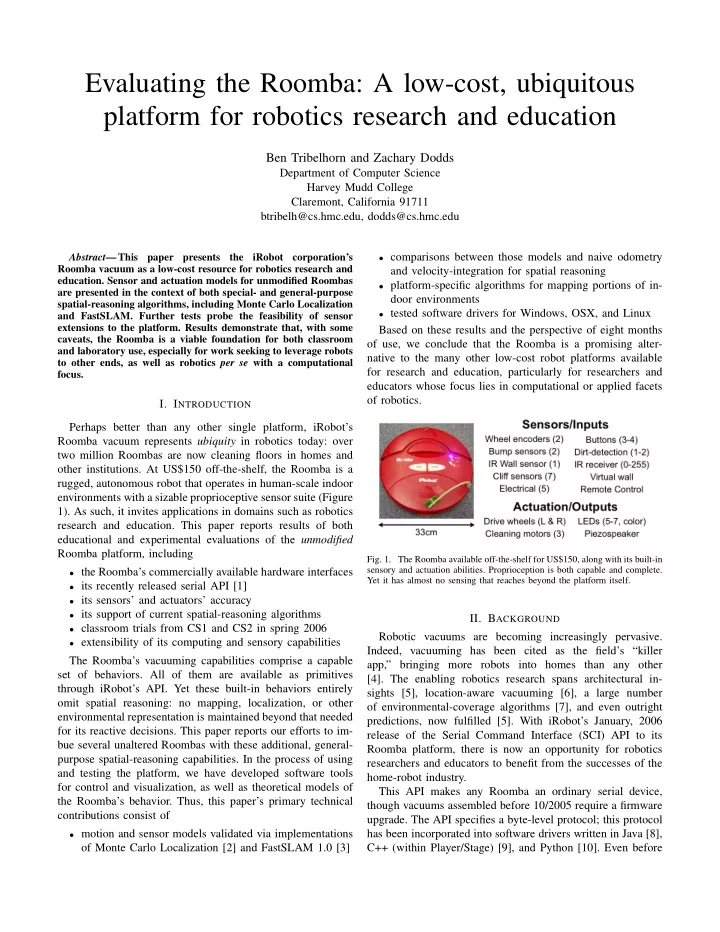
rugged, autonomous robot that operates in human-scale indoor environments with a sizable proprioceptive sensor suite (Figure 1). As such, it invites applications in domains such as robotics research and education. This paper reports results of both educational and experimental evaluations of the unmodified Roomba platform, including

  • the Roomba’s commercially available hardware interfaces
  • its recently released serial API [1]
  • its sensors’ and actuators’ accuracy
  • its support of current spatial-reasoning algorithms
  • classroom trials from CS1 and CS2 in spring 2006
  • extensibility of its computing and sensory capabilities

The Roomba’s vacuuming capabilities comprise a capable set of behaviors. All of them are available as primitives through iRobot’s API. Yet these built-in behaviors entirely

  • mit spatial reasoning: no mapping, localization, or other

environmental representation is maintained beyond that needed for its reactive decisions. This paper reports our efforts to im- bue several unaltered Roombas with these additional, general- purpose spatial-reasoning capabilities. In the process of using and testing the platform, we have developed software tools for control and visualization, as well as theoretical models of the Roomba’s behavior. Thus, this paper’s primary technical contributions consist of

  • motion and sensor models validated via implementations
  • f Monte Carlo Localization [2] and FastSLAM 1.0 [3]
  • comparisons between those models and naive odometry

and velocity-integration for spatial reasoning

  • platform-specific algorithms for mapping portions of in-

door environments

  • tested software drivers for Windows, OSX, and Linux

Based on these results and the perspective of eight months

  • f use, we conclude that the Roomba is a promising alter-

native to the many other low-cost robot platforms available for research and education, particularly for researchers and educators whose focus lies in computational or applied facets

  • f robotics.
  • Fig. 1. The Roomba available off-the-shelf for US$150, along with its built-in

sensory and actuation abilities. Proprioception is both capable and complete. Yet it has almost no sensing that reaches beyond the platform itself.

  • II. BACKGROUND

Robotic vacuums are becoming increasingly pervasive. Indeed, vacuuming has been cited as the field’s “killer app,” bringing more robots into homes than any other [4]. The enabling robotics research spans architectural in- sights [5], location-aware vacuuming [6], a large number

  • f environmental-coverage algorithms [7], and even outright

predictions, now fulfilled [5]. With iRobot’s January, 2006 release of the Serial Command Interface (SCI) API to its Roomba platform, there is now an opportunity for robotics researchers and educators to benefit from the successes of the home-robot industry. This API makes any Roomba an ordinary serial device, though vacuums assembled before 10/2005 require a firmware

  • upgrade. The API specifies a byte-level protocol; this protocol

has been incorporated into software drivers written in Java [8], C++ (within Player/Stage) [9], and Python [10]. Even before

slide-2
SLIDE 2

the release of the API, the worldwide community of robot enthusiasts had shown the platform’s promise [11] [12]. More recently, Bluetooth, USB, and RS232 serial interfaces have become commercially available [13]. Figure 2 summarizes these devices and their current costs.

  • Fig. 2.

Commercially available USB, RS232, and Bluetooth serial interfaces to the Roomba provide researchers and educators an inexpensive platform that requires no custom hardware or construction at all. When obtained with a Roomba, these devices are now US$10, $5, and $80, respectively [13].

With iRobot-based software support and third-party hard- ware interfaces, off-the-shelf Roombas are now programmati- cally accessible without any modification whatsoever. Whim- sical applications have emerged: the Roomba has also been adapted to playing the game Frogger on a busy street [14]. But it is not obvious that the Roomba can serve as a resource for validating researchers’ algorithms or enabling students to implement and experiment with those algorithms in a lab

  • setting. To our knowledge, this paper’s study is the first to

address these questions.

  • III. COMMUNICATION AND CONTROL
  • A. Hardware

The most flexible method of communication is Bluetooth which uses the unlicensed 2.4 GHz ISM (Industrial Scientific Medical) band. The aforementioned Bluetooth device (named the RooTooth) is Class 1, allowing a range up to 100 meters. Connection quality over distance drops slowly and our tests indicate that adequate connections can be made up to 60m. The number of Bluetooth devices that can be used simulta- neously is large, as there are 79 channels available. Our tests have demonstrated that a single laptop can easily interact at least five devices concurrently without reducing throughput to individual platforms.

  • B. Drivers

We have written two Python layers atop iRobot’s byte-level

  • interface. They provide full access to the Roomba’s sensors,

speaker, motors, and built-in behaviors. As shown in Figure 3,

  • ur top layer allows for straight-line translation and includes

an odometric correction model. We have also compared the Bluetooth and USB throughput using this Python layer. USB polling of all of the Roomba’s sensors averages an update rate of 66Hz; Bluetooth is con- siderably slower. A single Bluetooth module peaks at 16Hz in Fast Data Mode and 6Hz in its normal mode. A possible solution to this limit in bandwidth would be to mount a micro- controller which reacts to the sensors for stopping quickly and allows higher level decisions to be made by a remote computer which would make higher-level decisions less often.

  • Fig. 3.

The basic architecture of our Python driver.

This paper’s focus, however, is in maximizing the capabilities

  • f an unaltered Roomba platform.
  • C. Simulation

The Python Robotics (Pyro) toolset already has drivers to access the Roomba’s capabilities. In addition, the Roomba is controllable via the player/stage server/simulator. We have written our own simulator for the Roomba as a test bed for our algorithm implementations. This simple 2D interface enables visualization of all of the Roomba’s local sensing and is freely available at [15].

  • IV. ROOMBA MODELS

A small number of discrepancies between the Roomba’s published programming interface [1] and the platform’s be- havior motivated our own modeling of its actions and ac-

  • curacy. For instance, the API cites special codes to indicate

straight-line driving (SCI p.4). However, actual behavior did not differ from those commands’ large radius of curvature (ROC) limits, published at two meters. Discussions among many experimenters have confirmed the difficulty of straight- line motion through the API alone. Second, we found that Roombas within a single production run are quite consistent in their behavior. However, those across different major runs can be very different in their responses to identical API actuation commands under identical environmental conditions.

  • A. Odometric Modeling

One of the most important sensing capabilities of the Roomba is odometry. Unfortunately, there is a huge bias when translating left and right and turning around the maximum ROC (80◦ vs. −30◦ over 15s at 20cm/s). A software layer, RoombaDrive, compensates for this bias by allowing simple rotation and linear translation. Linear translation is achieved by time-slicing left and right turns at the maximum ROC. The left-bias time-slicing parameter is denoted α, with 0 < α < 1. Every half-second, α half-seconds are spent turning left, and 1 − α half-seconds are spent turning right.

slide-3
SLIDE 3
  • Fig. 4.

Regressions of translation and rotation show m to be the same for both of these types of motion for a specific Roomba, named Rsw. We found equations for distance and angle by integrating data from multiple robots, including robots from three different production runs.

Running various tests of our line driving and turning code allowed us to extract a motion model. In Figure 4, data from a single robot is depicted. Linear regressions of raw data versus actual position in linear translation and rotation shows that the slope m is constant between line driving and turning. We ran the tests over multiple robots and production runs and found this correlation to be consistent. We attempted to find a single robot-specific parameter to allow the calculation of m. It turned out that α, the lean to the left or right as described above, sufficed for this purpose. First, we ascertained α by time-slicing each robot’s largest ROC under various α values until we find one that results in straight-line translation. We then optimize a constrained quadratic relationship (Figure 5) to find a mapping from this α to m summarized in equation 1. The intercept value of c = −5 represents an empirically-tuned correction for the ”wobble” inherent in this method of straight-line translation. Like the relationship between α to m, this value did not vary among different platforms. m = 0.705 + α − α2 (1) Using equation 1, equations for distance and angle (r, θ) as functions of the raw data provided by the serial API [1] and the robot specific α become the following: r = distance 10.0 ∗ (0.705 + α − α2) − c (2)

  • Fig. 5.

Iterated regression of empirical data which provides equation 1.

θ = angle 129.0 ∗ (0.705 + α − α2) (3)

  • Fig. 6.

Comparison of basic kinematic odometry, velocity estimated

  • dometry, and our modeled odometry on two robots from separate batches.

For this sample N = 18. Figure 7 presents a closer comparison of basic

  • dometry versus modeled odometry.

Because the odometry is presented only incrementally, rapid odometric sampling will reduce the accuracy of these equations, especially for distance. In situations where it is necessary to sample multiple times per second, we remove the compensatory factor c from equation 2. Our working system samples odometry at every change in velocity. Results from additional testing of our motion model against basic odometry and velocity-based odometry are illustrated in Figures 6 and 7. The sampled error for naive odometry is σr = 11.5% and σθ = 12.4% which depends strongly on the specific robot (and might be correlated with α). Our corrected model has error of σr = 2.9% and σθ = 6.1%, significantly improving odometric accuracy. One caveat with our model is that tests with a hardware- altered Roomba (the main vacuum and brushes had been re-

slide-4
SLIDE 4
  • Fig. 7.

Here basic odometry is skewed in angular movement (x = 21.5%) and generally far less accurate than our modeled odometry.

moved) showed a larger m value that did not fit equation 1 due to a reduced drag factor. Changing the weight or dynamics of a Roomba thus requires remodeling of the resulting odometry.

  • B. Sensing Models

The Roomba only has local sensing in the form of bump and IR sensors. When the Roomba bumps an obstacle, it often slips as it pushes forward, causing the robot to rotate. This rotation is not measured by the odometry. It can be factored into larger error models used by higher-level control or estimation

  • software. The IR sensors can detect virtual walls (provided

with the Roomba) and cliffs. The bump sensors have four states which result from a left and right sensor attached to a single rigid bumper. Thus, these states are left, right, front, or no bump. The collision angle that will produce a front bump varies with the sampling rate. In the ideal, bumps within a forward-facing cone of ±20◦ cause both sensors to trigger (due to bumper rigidity). However at sampling rates of around 4Hz or less, a front bump will be detected at a range of ±60◦ or more. If the response to this bump is similarly slow, the robot will usually slip and actually end its motion facing the wall which can adversely effect odometry. This effect is mitigated, but not eliminated, by our modeled odometry.

  • V. ALGORITHMIC VALIDATION: MCL AND FASTSLAM

Monte Carlo Localization (MCL) is a probabilistic estima- tion of pose in a known map that combines range sensing and odometry [2]. Using only the tactile sensing on-board the Roomba we were able to implement and demonstrate successful pose tracking at AAAI 2006. Three snapshots from an example of a successful MCL run are shown in Figure 8; the full video is at [15].

  • Fig. 8. Recorded at AAAI 2006, this shows a Roomba successfully localizing

itself using MCL. In the middle image note that the wall in question is actually an IR-based virtual wall provided with the platform.

Our MCL implementation used an over-generous uniform model of motion error: 35% in distance and 25% in angle, in

  • rder to compensate for the inaccuracy of the naive kinematic
  • model. Recall that when driving in large arcs the Roomba is

extremely biased even while reporting symmetrically identical

  • dometric readings. Thus, this large, uniform error creates a

cloud of particles to cover probable locations. Successful runs generally used 300 particles. Because of many applications’ preference for piecewise linear motion, building a motion model of arcs is not always

  • f primary importance. Instead, using the straight-line driving

modeled in Section IV, we experimented further with mapping algorithms, as detailed in the next section.

  • VI. ROOMBA MAPPING

Mapping with the Roomba presents a stiff challenge. Given the lack of onboard computation and lack of range sensing, mapping is nontrivial. We have designed a preliminary set of mapping algorithms using only local sensing and odometry. What makes them possible is the strong a priori knowledge that we assume:

  • A typically indoor, human-scale environment consisting
  • nly of walls (and other line segments).
  • All such walls and segments are parallel or perpendicular.

These assumptions allow many naive interpretations of the incoming data. For instance, one could fit a line to raw

  • dometry data recorded at each of the Roomba’s wall-bumps

(the naive algorithm). Our online Roomba-based mapping models each wall as an ellipse and uses our improved model of reported odometry and straight-line driving. Here we present

slide-5
SLIDE 5
  • ur algorithm and contrast the results of our approach in

comparison with the naive one.

  • A. Roomba-specific mapping

In the general case of N walls, each bump is a unit of information that is added to our map. We initially begin with

  • ne wall. Starting with the second collision we minimize the

increase in uncertainty over all walls by limiting the minor axis

  • f the wall to a Roomba’s diameter (33cm) and the standard

deviation of collision angles to 0.5 radians. If the latest bump location does not fit any wall within these threshholds, a new wall is added to the map. Our results for small runs of eight or fewer bumps align the walls after collecting all the data. Wall alignment uses the angle of the first wall to rotate the second wall and each subsequent wall uses the angle of the previous wall to align

  • itself. This works well for small samples, however around

seven or eight collisions corrections to incoming data must be made or else wall uncertainty will become too large and the algorithm will hallucinate erroneous walls. Thus, to correct larger samples, we begin throwing out

  • ld points when fitting new data. This method incorporates

enough history to always have a best fit (three points per wall) while stressing the ground truth of each bump reading. The following descriptions contrast the maps made using the naive (raw odometry) and improved (Section IV odometry) models. Case 1: (single wall) Fitting a line to a set of points is trivial and both the naive and improved odometric models performed well. Case 2: (a corner) Basic odometry shows slightly better results and less global skew. As is clear in Figure 9, single- corner finding is not difficult.

  • Fig. 9.

Blue: Basic odometry. Red: Modeled odometry. Enforcing perpen- dicularity of walls, both sets of odometric readings find the corner, and both finish close to the true wall-relative location.

Case 3: (a hallway) With a set of five collisions, our

  • dometry model found nearly parallel walls and estimated the

distance between them to be 181cm. The actual distance is

  • 180cm. Basic odometry, in contrast, estimated that the hallway

walls were perpendicular and found three walls; the uncon- strained fit is depicted in Figure 11. Figure 12 shows naive

  • dometry from a longer hall run. We are able to find parallel

walls as illustrated in Figure 13. With the large data sample correction, our modeled odometry estimates the hallway to be 184.8cm and naive odometry estimates 201.4cm, again with a true 180cm distance. Complete results are listed in Table

  • 10. Our modeled odometry - not designed for the purpose
  • f mapping but for the purpose of straight-line translation -

demonstrates a significant improvement in accuracy. Line fitting Modeled Naive short run 181.0 ± 3.0cm 194.1 ± 101.9cm* long run 184.8 ± 124.1cm 201.4 ± 40.9cm

  • Fig. 10.

Center-to-center distances from hallways cases depicted in Figures 11 and 13. The expected hallway distance is 180cm. Reported error is the average of the minor axes of the ellipses fit to the walls (three most recent points of each wall). *This distance is from the centers of orthogonal walls.

  • Fig. 11.

Unconstrained wall fitting shows modeled odometry to be signifi- cantly better than naive odometry.

  • Fig. 12.

Here naive odometry is skewed far to the right and our corrected

  • dometry is skewed nearly as much to the left. This run includes 15 bumps

in a hallway where the Roomba traveled about 10 meters from its starting location.

  • B. FastSLAM

We also implemented FastSLAM 1.0 with known data correspondence as detailed in Probabilistic Robotics. We used a hallway and a simple wandering algorithm to ensure that

slide-6
SLIDE 6
  • Fig. 13.

As relative position is all that matters the correlated hallways have changed position as the odometry continues to gain more error. By only using the last six bumps, a fit can be maintained down a long hallway.

alternating bumps corresponded to each of the two walls, in

  • turn. The walls themselves serve as FastSLAM’s landmarks.

While a naive adaptation of FastSLAM might ignore the angle

  • f the walls and to assume that the location of the feature is

the center of the wall, the results from such a method are not very useful for mapping because they are highly uncertain and do not contain relative angular information. Thus, our implementation of FastSLAM uses the feature’s covariance matrix to model both the angle and uncertainty of a wall, and the point location is then used as the center of the wall. Unfortunately, longer runs suffer from considerable angular drift which degrades the results. As before, only the three most recent points of a wall are used to calculate the uncertainty ellipse. However, unlike our line-fitting algorithm, with FastSLAM the earlier points impact the current ellipses because the movement of each landmark depends on the current covariance at every step. This difference proves to be the key distinction between our algorithm and FastSLAM. To compare the two, we report the single metric parameter estimated by both algorithms, i.e., the estimated distance between the walls. Results from FastSLAM are listed in Table 14. Not surprisingly, because our alternative approach is so closely coupled with the platform on which it is running, it results in improved accuracy in estimating the inter-wall distance of a hallway. This paper’s purpose, however, is not to propose a ”correct” mapping algorithm for the Roomba, but to investigate the Roomba’s ability to support algorithms of current interest to the community. In addition, the platform scales well pedagogically: it supports probabilistic investiga- tions as ably as it does reactive architectures. Such scalability is unusual in low-cost platforms.

  • VII. PLATFORM EXTENSIONS

As a result, in conjunction with our odometric models and software drivers, the Roomba is a viable low-cost solution for robotics and AI applications and education. Our algorithmic results demonstrate the ability and promise of this platform. FastSLAM Modeled Basic short run 158.4 ± 3.0cm 185.1 ± 101.9cm long run 99.5 ± 124.1cm 155.3 ± 40.9cm short (ellipses) 181.5 ± 3.0cm 278.6 ± 101.9cm long (ellipses) 298.7 ± 124.1cm 570.5 ± 40.9cm

  • Fig. 14.

Wall distances from the hallway cases depicted in Figures 11 and 12. The expected hallway distance is 180cm and all results save one have this distance within their uncertainty. The best data fit is the short run using corrected odometry and ellipse fitting which is the only one to have a reasonable amount of error. Reported error is the average of the minor axes

  • f the ellipses fit to the walls; given the significant odometric skew for these

long runs, large errors are unsurprising.

Yet there are drawbacks: the two most important are the lack

  • f onboard computation (when, as here, it is used as a serial

device) and its lack of range sensing. This section describes methods for overcoming these issues.

  • A. Computation

A very important feature of any AI device is computational

  • power. Many controllers are available to add this “AI-umph”

to the Roomba. PDAs, Gumstix, and micro-controllers are common additions to small mobile robots. One of our solutions is to velcro a laptop to the top of the Roomba. Mounting a laptop on the top the of the robot did not reduce the motors’ performance noticeably. At higher speeds, a less precarious solution is to mount a wireless camera on the robot and continue to run the computation off the Roomba itself.

  • B. Sensing

Using Mac OS X as this project’s primary development environment, we have devloped a C library that enables access to the YUV pixel values provided by the iSight camera (or any

  • ther QuickTime input) [15]. Prior work in this area has not

allowed for pixel-level access of values [16]. This development along with the laptop mounted on the Roomba enabled us to implement and run FastSLAM using visual input data with artificial landmarks placed in the environment. An approach taken by Brian Gerkey [11] for augmenting the Roomba’s capabilities adds a laser range finder atop the vacuum’s enclosure. This served as the basis for another slam approach, using the algorithms provided as part of Player/Stage. It’s noteworthy that the sensor in this case increases the cost of the total system by more than an order

  • f magnitude.

An alternative and very low-cost means to obtain single- point range data is to use an onboard camera and a laser pointer, which prior work has shown can provide excellent accuracy for the price (less than 5% error at 4m for US$40) [17] .

  • VIII. EDUCATIONAL TRIALS

The Roomba was used as the basis for several assignments in a CS1/CS2 course sequence taught at Chatham College, an all-women’s institution in Pittsburgh, PA. Low cost was one reason for choosing the Roomba. Yet a much more important reason was that, as a serial device, the Roomba integrated

slide-7
SLIDE 7

effortlessly into the Python-based environment in which these courses were being taught. This CS1/CS2 trial included an external assessment effort to determine the extent to which the Roomba (and robots in general) affected students’ feelings and capabilities in learning introductory computer science. The results have shown that the physical interactions had a significant impact. One student indicated that the impact was intellectual: Like when you’re just working on the screen it’s like ‘oh the little dot is moving.’ When you’re working with the actual thing [the Roomba], you’re like okay, problem solving. Because it’s a lot easier to solve the problem if it’s 3D, in front of you, and you can see exactly what the problem is. Another student described the robot’s impact in affective terms: “Playing with the Roomba made it a lot more fun.” A third student pointed to overcoming some of the Roomba’s idiosyncracies when asked Which activities do you think have been most useful this semester in making you a better programmer?: I would say that probably working with the Roomba definitely just because the first day we worked with it we were trying to get it to go in a straight line because it has like a natural curve to it so it doesn’t go straight. Overall, the Roomba added excitement to the classes, and it provided hands-on, task-specific applications for the program- ming concepts covered. Moreover, the Roomba did not add the time-intensive overhead of constructing and maintaining Lego-based or other hand-built platforms, nor did it require us to change the programming language or OS on which the class was based. In contrast to many of the other platforms in Figure 15, the Roomba can be used to support an existing CS and AI curriculum, rather than requiring a curriculum designed especially for it.

  • IX. PERSPECTIVE

These extensions and applications of the Roomba only scratch the surface of what is possible, enabling users an inexpensive basis on which to design systems that run “with

  • ur initiation, but without our intervention.” [5] As this paper

demonstrates, even the ubiquitous, unmodified Roomba plat- form can support far more than the vacuuming tasks for which it was designed. As an educational resource, the Roomba is pedagogically scalable: it is as suitable for reinforcing begin- ning programming concepts as it is for exploring algorithms

  • f current interest to the robotics community. As a research

resource, the Roomba empowers investigators who want to use robots, rather than build them. For example, it offers researchers involved in the fields of multi-agent systems, HRI,

  • r many other subfields of AI and CS an off-the-shelf means

to embody and test their work without having to spend time constructing or modifying hardware. Ultimately, the Roomba offers the robotics community both an example of the widespread commercial viability of Platform Cost Sensing Lego RCX $200 Bmp,Lt Roomba $230 Vis,Mic,Bmp,Enc,WL Lego NXT $250 Bmp,Lt,Son,Enc,WL Intellibrain $300 Bmp,Lt,IR,a2d,WL PalmPRK $325 IR,a2d HandyBoard $350 Bmp,Lt,IR,a2d KIPR XBC $500 Vis,Bmp,Lt,IR,Enc UMN eRosi $500 Lt,Enc,Pyr,WL HandyBoard2 $750 Vis,Bmp,Lt,IR,Enc,a2d,WL Hemisson $780 Lt,IR,WL Garcia $1725 Vis,IR,Enc,WL Khepera $2000 IR,Enc AIBO $2000 Vis,Mic,Bmp,Enc,WL

  • Fig. 15.

A comparison of several inexpensive robot platforms/controllers, their costs, and their standard set of sensing capabilities. Legend: Bmp, bump or tactile sensing; Lt, light sensing; Vis, vision; Mic, microphone; Enc, encoders or odometry; WL, wireless communication with a controlling PC; a2d, general analog/digital inputs; IR, infrared range sensing; Pyr, heat or flame sensing;

autonomous robots and a novel resource we can leverage toward our educational and research goals. It heralds the advent of robotic peripherals that can take advantage of all of the computing power and cost-efficiency of today’s commodity laptop and desktop machines. This paper provides an improved odometric model of the Roomba, some strategies for handling its idiosyncrasies, and and an initial assessment of the Roomba’s capabilities. We believe it won’t be long before there emerge a wide variety of applications of this modest platform.

  • X. ACKNOWLEDGMENTS

This work was made possible by funds from NSF DUE #0536173, as well as funding and resources from Harvey Mudd College and Chatham College. REFERENCES

[1] Roomba Serial Command Interface (SCI) Specification, iRobot, 2006. [Online]. Available: http://www.irobot.com/hacker [2] S. Thrun, D. Fox, W. Burgard, and F. Dellaert, “Robust monte carlo localization for mobile robots,” Artificial Intelligence, vol. 128, no. 1-2,

  • pp. 99–141, 2001.

[3] M. Montemerlo, S. Thrun, D. Koller, and B. Wegbreit, “FastSLAM: A factored solution to the simultaneous localization and mapping problem,” in Proceedings of the AAAI National Conference on Artificial Intelligence. Edmonton, Canada: AAAI, 2002. [4] L. Grossman, “Maid to order,” Time Magazine, vol. September, 2002. [5] R. Brooks, “Achieving Artificial Intelligence through Building Robots,” Massachusetts Institute of Technology, Cambridge, MA, AI-Memo 899,

  • Tech. Rep., 1986.

[6] S. Domnitcheva, “Smart vacuum cleaner - an autonomous location-aware cleaning device,” in Adjunct proceedings, Sixth Int. Conf. on Ubiquitous Computing (UbiComp), 2004. [7] H. Choset, K. Lynch, S. Hutchinson, G. Kantor, W. Burgard, L. Kavraki, and S. Thrun, Principles of Robot Motion: Theory, Algorithms, and Implementations. MIT Press., 2005. [8] T. Kurt, Hacking Roomba: ExtremeTech. Wiley, 2006, to appear. [9] B. Gerkey, R. T. Vaughan, and A. Howard, “The player/stage project: Tools for multi-robot and distributed sensor systems,” in In Proceedings

  • f the 11th International Conference on Advanced Robotics (ICAR),

2003, pp. 317–323.

slide-8
SLIDE 8

[10] Z. Dodds and B. Tribelhorn, “Erdos: Cost effective peripheral robotics for ai education,” in Proceedings, AAAI, 2006, pp. 1966–1967. [11] B. Gerkey, “Mapping with the iRobot Roomba,” 2006. [Online]. Available: http://www.ai.sri.com/∼gerkey/roomba/index.html [12] P. Mecklenburg, “Roomba SLAM,” 2005. [Online]. Available: http://www.cs.unc.edu/∼prm/roomba/roomba-slam.pdf [13] “RoombaDevTools,” 2006. [Online]. Available: http://www.roombadevtools.com [14] P. Torrone, “Roomba Tronic,” Make Magazine, vol. 06: Robots, 2006. [15] Z. Dodds and B. Tribelhorn, “Erdos,” 2006. [Online]. Available: http://www.cs.hmc.edu/∼dodds/erdos [16] D. Heckenberg, “Using Mac OS X for Real-Time Image Processing,” in Proceedings of the Apple University Consortium Conference, 2003. [17] A. Davidson, B. Tribelhorn, T. Leung, and Z. Dodds, “Low-Cost Range Sensing for Laptop Robots,” in Proceedings of the IASTED Conference

  • f Robotics and Applications, 2005, pp. 329–333.