
SLIDE 1
Evaluating and Treating DNAPL in Fractured Rock
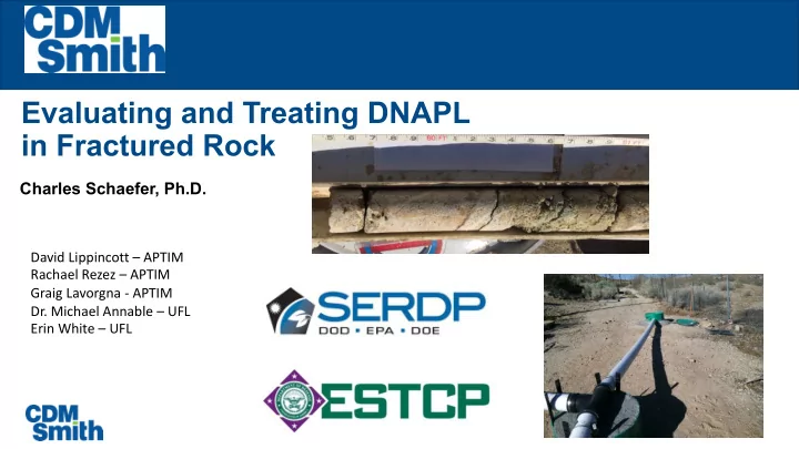
Charles Schaefer, Ph.D.
David Lippincott – APTIM Rachael Rezez – APTIM Graig Lavorgna - APTIM
- Dr. Michael Annable – UFL
Evaluating and Treating DNAPL in Fractured Rock Charles Schaefer, - - PowerPoint PPT Presentation
Evaluating and Treating DNAPL in Fractured Rock Charles Schaefer, Ph.D. David Lippincott APTIM Rachael Rezez APTIM Graig Lavorgna - APTIM Dr. Michael Annable UFL Erin White UFL DNAPL Architecture, Dissolution, and Treatment
Influent manifold connected to HPLC pump. Typical flow
Effluent collection
Rock Residual Saturation (cm3/cm3) Interfacial Area (cm2/cm3) Colorado 1 0.24 21 Colorado 2 0.21 48 Arizona 1 0.39 56 Arizona 2 0.43 20
0.0000 0.0006 0.0012 0.0018 0.0024 0.01 0.02 0.03 0.04 0.05 0.06
Intrinsic Mass Transfer Coefficient (cm/min) Re
A1 C1 A2 C2
0.0 0.2 0.4 0.6 0.8 1.0 1.2 100 200 300 400 500 600 C/C0 Total Minutes SDBS Bromide 0.2 0.4 0.6 0.8 1 1.2 200 400 600 800 1000 1200 C/Co Total Minutes SDBS Br
Ø
Ø
Ø
Ø
Ø
Ø
Ø
60 65 70 75 80 85 90
ft bgs
Pu ~13
Annable et al., JEE, 1998
60 65 70 75 80 85 90
B06 B07
ft bgs
B11
Pu ~13
Low T
Based on conceptual model by Parker et al., 1994
0.0 0.1 0.2 0.3 10 20 30
0.00 0.01 0.02 0.03 0.04 0.0 0.5 1.0 1.5 2.0 2.5
Relative Concentration (C/C0) Time Elapsed (days)
24DMP Bromide
2 4 6 8 10 50 100 150 200
Distance Inward from Fracture (cm) PCE Concentration (µg/kg)
76 ft bgs 98 ft bgs
100 200 300 400 500 200 400 600 800
Sulfate (mg/L) Days
100 200 300 400 500 200 400 600 800
Sulfate (mg/L) Days
3 6 9 12 200 400 600 800
Dissolved Fe (mg/L) Days
3 6 9 12 200 400 600 800
Dissolved Fe (mg/L) Days
G W r e c i r c Bioaugment End G W r e c i r c Bioaugment End
1.E+00 1.E+01 1.E+02 1.E+03 1.E+04 1.E+05 1.E+06 1.E+07 200 400 600 800
DHC (cell/mL) Elapsed Time (days)
1.E+00 1.E+01 1.E+02 1.E+03 1.E+04 1.E+05 1.E+06 1.E+07 200 400 600 800
DHC (cell/mL) Date
G W r e c i r c End G W r e c i r c Bioaugment End
1000 2000 3000 200 400 600 800
Propionic Acid (mg/L) Days
1000 2000 3000 200 400 600 800
Propionic Acid (mg/L) Days
G W r e c i r c Bioaugment End G W r e c i r c Bioaugment End
1.E-05 1.E-04 1.E-03 1.E-02 1.E-01 1.E+00 1.E+01 200 400 600 800
PCE TCE DCE VC Ethene
G W r e c i r c End Bioaugment
1.E-05 1.E-04 1.E-03 1.E-02 1.E-01 1.E+00 200 400 600 800
PCE TCE DCE VC Ethene
G W r e c i r c Bioaugment End
50 100 150 200 100 200 300 400 500
Generated Chloride (mg/L) Days
Bioaugment End
0.001 0.010 0.100 1.000 10 20 30
Relative Concentration (C/C0) Time Elapsed (days)
24DMP Bromide
0.001 0.010 0.100 1.000 10 20 30
Relative Concentration (C/C0) Time Elapsed (days)
24DMP Bromide