ethernet switches
play

Ethernet Switches layer 2 (frame) forwarding, filtering using LAN - PDF document

Ethernet Switches layer 2 (frame) forwarding, filtering using LAN addresses Switching: A-to-B and A-to- Medium Access Layer B simultaneously, no collisions large number of interfaces often: individual hosts, star-


  1. Ethernet Switches • layer 2 (frame) forwarding, filtering using LAN addresses • Switching: A-to-B and A’-to- Medium Access Layer B’ simultaneously, no collisions • large number of interfaces • often: individual hosts, star- connected into switch – Ethernet, but no collisions! Ethernet Switches 
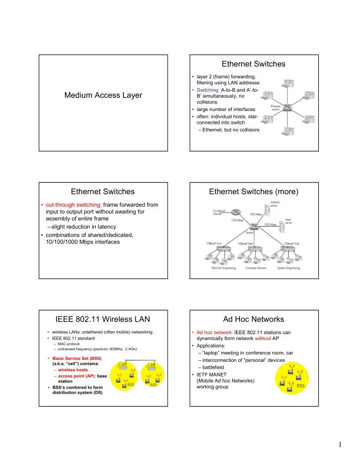
Ethernet Switches (more) • cut-through switching: frame forwarded from Dedicated input to output port without awaiting for assembly of entire frame Shared –slight reduction in latency • combinations of shared/dedicated, 10/100/1000 Mbps interfaces IEEE 802.11 Wireless LAN Ad Hoc Networks • wireless LANs: untethered (often mobile) networking • Ad hoc network: IEEE 802.11 stations can • IEEE 802.11 standard: dynamically form network without AP – MAC protocol • Applications: – unlicensed frequency spectrum: 900Mhz, 2.4Ghz – “laptop” meeting in conference room, car • Basic Service Set (BSS) – interconnection of “personal” devices (a.k.a. “cell”) contains: – battlefield – wireless hosts • IETF MANET – access point (AP): base (Mobile Ad hoc Networks) station working group • BSS’s combined to form distribution system (DS) 1

  2. IEEE 802.11 MAC Protocol: IEEE 802.11 MAC Protocol CSMA/CA 802.11 CSMA: sender 802.11 CSMA Protocol: others - if sense channel idle for DIFS sec. • NAV : Network Allocation Vector then transmit entire frame (no collision detection) • 802.11 frame has transmission time field -if sense channel busy then binary backoff • others (hearing data) defer access for NAV time units 802.11 CSMA receiver: if received OK return ACK after SIFS Collision Avoidance: RTS-CTS Hidden Terminal effect exchange • hidden terminals: A, C cannot hear each other • CSMA/CA: explicit channel – obstacles, signal attenuation reservation – collisions at B – sender: send short RTS: request to send • goal: avoid collisions at B – receiver: reply with • CSMA/CA: CSMA with C ollision Avoidance short CTS: clear to send • CTS reserves channel for sender, notifying (possibly hidden) stations • avoid hidden station collisions Collision Avoidance: RTS-CTS Point to Point Data Link Control exchange • one sender, one receiver, one link: easier • RTS and CTS short: than broadcast link: – collisions less likely, – no Media Access Control of shorter duration – no need for explicit MAC addressing – end result similar to collision detection – e.g., dialup link, ISDN line • IEEE 802.11 allows: • popular point-to-point DLC protocols: – CSMA – PPP (point-to-point protocol) – CSMA/CA: – HDLC: High level data link control (Data reservations link used to be considered “high layer” in protocol stack! – polling from AP 2

  3. PPP non-requirements PPP Design Requirements [RFC 1557] • packet framing: encapsulation of network-layer • no error correction/recovery datagram in data link frame – carry network layer data of any network layer • no flow control protocol (not just IP) at same time • out of order delivery OK – ability to demultiplex upwards • no need to support multipoint links (e.g., • bit transparency: must carry any bit pattern in the data field polling) • error detection (no correction) Error recovery, flow control, data re-ordering • connection livenes: detect, signal link failure to all relegated to higher layers!| network layer • network layer address negotiation: endpoint can learn/configure each other’s network address PPP Data Frame PPP Data Frame • Flag: delimiter (framing) • info: upper layer data being carried • Address: does nothing (only one option) • check: cyclic redundancy check for error detection • Control: does nothing; in the future possible multiple control fields • Protocol: upper layer protocol to which frame delivered (eg, PPP-LCP, IP, IPCP, etc) Byte Stuffing Byte Stuffing • “data transparency” requirement: data field must be allowed to include flag pattern flag byte <01111110> pattern in data – Q: is received <01111110> data or flag? to send • Sender: adds (“stuffs”) extra < 01111110> byte after each < 01111110> data byte • Receiver: – two 01111110 bytes in a row: discard first flag byte pattern plus byte, continue data reception stuffed byte in transmitted data – single 01111110: flag byte 3

  4. PPP Data Control Protocol Asynchronous Transfer Mode: ATM Before exchanging • 1980s/1990’s standard for high-speed network-layer data, data (155Mbps to 622 Mbps and higher) Broadband link peers must Integrated Service Digital Network architecture • configure PPP link (max. • Goal: integrated, end-end transport of carry frame length, voice, video, data authentication) – meeting timing/QoS requirements of voice, • learn/configure network video (versus Internet best-effort model) layer information – “next generation” telephony: technical roots – for IP: carry IP Control in telephone world Protocol (IPCP) msgs – packet-switching (fixed length packets, (protocol field: 8021) called “cells”) using virtual circuits to configure/learn IP address ATM architecture ATM: network or link layer? Vision: end-to-end transport: “ATM from desktop to desktop” – ATM is a network technology Reality: used to • adaptation layer: only at edge of ATM network connect IP – data segmentation/reassembly backbone routers – roughly analogous to Internet transport layer – “IP over ATM” • ATM layer: “network” layer – ATM as switched – cell switching, routing link layer, • physical layer connecting IP routers ATM Adaptation Layer (AAL) ATM Adaption Layer (AAL) [more] • ATM Adaptation Layer (AAL): “adapts” upper layers Different versions of AAL layers, depending on ATM service (IP or native ATM applications) to ATM layer below class: • AAL1: for CBR (Constant Bit Rate) services, e.g. circuit emulation • AAL present only in end systems , not in switches • AAL2: for VBR (Variable Bit Rate) services, e.g., MPEG video • AAL layer segment (header/trailer fields, data) • AAL5: for data (eg, IP datagrams) fragmented across multiple ATM cells User data – analogy: TCP segment in many IP packets AAL PDU ATM cell 4

  5. AAL5 - Simple And Efficient AL ATM Layer (SEAL) Service: transport cells across ATM network • AAL5 : low overhead AAL used to carry IP • analogous to IP network layer datagrams • very different services than IP network layer – 4 byte cyclic redundancy check Guarantees ? Network Service Congestion Bandwidth Loss Architecture Model Order Timing feedback – PAD ensures payload multiple of 48bytes – large AAL5 data unit to be fragmented into 48-byte Internet best effort none no no no no (inferred via loss) ATM cells ATM CBR constant yes yes yes no rate congestion ATM VBR guaranteed yes yes yes no rate congestion ATM ABR guaranteed no yes no yes minimum none no ATM UBR yes no no ATM Layer: Virtual Circuits ATM VCs • VC transport: cells carried on VC from source to • Advantages of ATM VC approach: dest – QoS performance guarantee for connection – call setup, teardown for each call before data can flow mapped to VC (bandwidth, delay, delay jitter) – each packet carries VC identifier (not destination ID) • Drawbacks of ATM VC approach: – every switch on source-dest path maintain “state” for each passing connection – Inefficient support of datagram traffic – link,switch resources (bandwidth, buffers) may be – one PVC between each source/dest pair) does not allocated to VC: to get circuit-like perf. scale (N*2 connections needed) • Permanent VCs (PVCs) – SVC introduces call setup latency, processing – long lasting connections overhead for short lived connections – typically: “permanent” route between to IP routers • Switched VCs (SVC): – dynamically set up on per-call basis ATM Layer: ATM cell ATM cell header • 5-byte ATM cell header • VCI: virtual channel ID • 48-byte payload – will change from link to link thru net – Why?: small payload -> short cell-creation delay • PT: Payload type (e.g. RM cell versus data cell) for digitized voice • CLP: Cell Loss Priority bit – halfway between 32 and 64 (compromise!) – CLP = 1 implies low priority cell, can be discarded if congestion Cell header • HEC: Header Error Checksum – cyclic redundancy check Cell format 5

Download Presentation
Download Policy: The content available on the website is offered to you 'AS IS' for your personal information and use only. It cannot be commercialized, licensed, or distributed on other websites without prior consent from the author. To download a presentation, simply click this link. If you encounter any difficulties during the download process, it's possible that the publisher has removed the file from their server.

Recommend


More recommend