
5: DataLink Layer 5a-1
14: Ethernet, Hubs, Bridges, Switches, Other Technologies used at the Link Layer, ARP
Last Modified: 4/9/2003 1:14:12 PM
5: DataLink Layer 5a-2
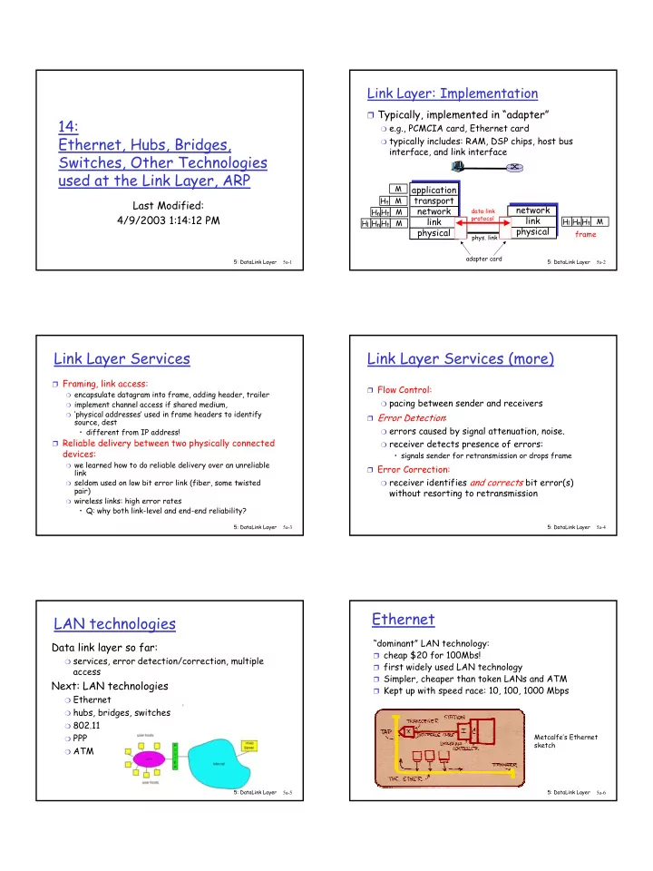
Link Layer: Implementation
❒ Typically, implemented in “adapter”
❍ e.g., PCMCIA card, Ethernet card ❍ typically includes: RAM, DSP chips, host bus
interface, and link interface application transport network link physical network link physical
M M M M Ht Ht Hn Ht Hn Hl M Ht Hn Hl frame
- phys. link
data link protocol adapter card
5: DataLink Layer 5a-3
Link Layer Services
❒ Framing, link access:
❍ encapsulate datagram into frame, adding header, trailer ❍ implement channel access if shared medium, ❍ ‘physical addresses’ used in frame headers to identify
source, dest
- different from IP address!
❒ Reliable delivery between two physically connected
devices:
❍ we learned how to do reliable delivery over an unreliable
link
❍ seldom used on low bit error link (fiber, some twisted
pair)
❍ wireless links: high error rates
- Q: why both link-level and end-end reliability?
5: DataLink Layer 5a-4
Link Layer Services (more)
❒ Flow Control:
❍ pacing between sender and receivers
❒ Error Detection:
❍ errors caused by signal attenuation, noise. ❍ receiver detects presence of errors:
- signals sender for retransmission or drops frame
❒ Error Correction:
❍ receiver identifies and corrects bit error(s)
without resorting to retransmission
5: DataLink Layer 5a-5
LAN technologies
Data link layer so far:
❍ services, error detection/correction, multiple
access
Next: LAN technologies
❍ Ethernet ❍ hubs, bridges, switches ❍ 802.11 ❍ PPP ❍ ATM
5: DataLink Layer 5a-6
Ethernet
“dominant” LAN technology:
❒ cheap $20 for 100Mbs! ❒ first widely used LAN technology ❒ Simpler, cheaper than token LANs and ATM ❒ Kept up with speed race: 10, 100, 1000 Mbps
Metcalfe’s Ethernet sketch