ES/EG 4546 Simple low cost Local Area Network (LAN) The Ethernet - - PowerPoint PPT Presentation

es eg 4546
SMART_READER_LITE
LIVE PREVIEW

ES/EG 4546 Simple low cost Local Area Network (LAN) The Ethernet - - PowerPoint PPT Presentation

What is a LAN? Ethernet A Local Area Network is.... ES/EG 4546 Simple low cost Local Area Network (LAN) The Ethernet Shared or Switched Access local (one building, group of buildings, etc) Local Area Network Supports : always controlled by one


slide-1
SLIDE 1

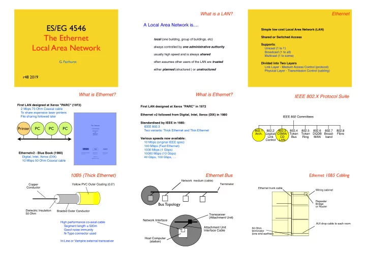
ES/EG 4546 The Ethernet Local Area Network

  • G. Fairhurst

r48 2019

What is a LAN?

local (one building, group of buildings, etc) always controlled by one administrative authority usually high speed and is always shared

  • ften assumes other users of the LAN are trusted

either planned (structured ) or unstructured

A Local Area Network is.... Ethernet

Simple low cost Local Area Network (LAN) Shared or Switched Access Supports: Unicast (1 to 1) Broadcast (1 to all) Multicast (1 to some) Divided into Two Layers Link Layer - Medium Access Control (protocol) Physical Layer - Transmission Control (cabling)

What is Ethernet?

First LAN designed at Xerox "PARC" (1972) 2 Mbps 75 Ohm Coaxial cable To share expensive laser printers File sharing followed later Ethernetv2 - Blue Book (1980) Digital, Intel, Xerox (DIX) 10 Mbps 50 Ohm Coaxial cable

Printer PC PC PC

What is Ethernet?

Standardised by IEEE in 1985: IEEE 802.3 Two variants: Thick Ethernet and Thin Ethernet Various speeds now available: 10 Mbps (original IEEE spec) 100 Mbps (Fast Ethernet) 1000 Mbps (1 Gbps) 10000 Mbps (10 Gbps) 40 Gbps, 100 Gbps, … First LAN designed at Xerox "PARC" in 1972 Ethernet v2 followed from Digital, Intel, Xerox (DIX) in 1980

IEEE 802.X Protocol Suite

IEEE 802 Committees 802.1 Arch. 802.3 CSMA/ CD LAN 802.4 Token Bus 802.5 Token Ring 802.6 DQDB MAN 802.2 Logical Link Control 802.7 Broad- band 802.8 Fibre

10B5 (Thick Ethernet)

!Yellow PVC Outer Coating (0.5") Dielectric Insulation 50 Ohm Copper Conductor Braided Outer Conductor High performance co-axial cable Segment length ≤ 500m Good noise immunity N-Type connector used In-Line or Vampire external transceiver

Ethernet Bus

Bus Topology

Network medium (cable) Terminator

Host Computer (station) Network Interface Transceiver (Attachment Unit) Attachment Unit Interface Cable

Ethernet 10B5 Cabling

Ethernet trunk cable AUI drop cable to each room 50 Ohm terminator (one end earthed) Wiring cabinet Repeater Bridge

  • r Router
slide-2
SLIDE 2

10B5 (Thick Ethernet Transceiver)

50 ohm terminator Attachment Unit Interface (AUI) Drop Cable 0 - 50 m

Host AUI Port

N-type Connectors In-Line Transceiver 15 pin AUI D-Connector

Host AUI Port

Vampire Transceiver Vampire Cable Tap

10B5 (Thick Ethernet Vampire Transceiver)

2-Part Block Holds Cable Insulated Spike Pierces Centre Core Shorter Spikes Cut into Outer Conductor Cable Transceiver Block MAU Bolt to Tighten Block Thick Wire (Yellow) Ethernet Cable

10B2 (Thin Ethernet)

!White, Grey or Black PVC Outer Coating Copper Conductor Dielectric Insulation 50 Ohm Braided Outer Conductor Low cost co-axial cable Segment length ≤ 185 m Flexible, easy installation BNC connector and “T” joiner In-built or external transceiver difficult to manage (unstructured)

Ethernet 10B2 Cabling

Wiring cabinet Repeater Bridge

  • r Router

Terminator Terminator One bus: No loops or stubs!

10 Base Fibre

Fibre Optic Cable

Used for pt-to-pt links Segment length ≤1 km (or more) Two diameters of fibre: Multimode (Thicker, Local networks) Single Mode (Thin, Longer distance) All types of fibre provide: High noise immunity No electrical path (protected from lightning) (secure, hard to tap-into) Uses external transceiver (i.e. connects a pair of repeaters) Easy to upgrade transceiver speed

10 Base Fibre

AUI connector

  • n equipment

10BF transceiver Pair of fibres (62.5/125 ) LED laser transmitter Photo diode detector

Ethernet Success Story

Cost-Effective Simple to use Familiarity to customers Standard for Internet LANs

Medium Access Control Frames Addressing Shared Access

CRC preamble 8 bytes 4 bytes packet of data to be sent 46 -1500 bytes destination address source address type 14 bytes

Link Layer

MAC Medium Access Control

Frames

  • Data is sent on an Ethernet Network in Frames

Addressing

  • All End Systems have an Ethernet MAC Address (In their “PROM”)
  • Each frame sent with this source address
  • Frames also carry a Destination Address, used in three ways:

Broadcast, Unicast, and Multicast Shared Access

  • Sharing network cost
  • Sharing the reachability

CRC preamble 8 bytes 4 bytes packet of data to be sent 46 -1500 bytes destination address source address type 14 bytes

slide-3
SLIDE 3

Ethernet Frames

Protocol Data Unit, PDU (Internet Packets) Encapsulated by Ethernet Frames to cross the LAN Adds 26 bytes of overhead to each PDU

CRC preamble 8 bytes 4 bytes packet of data to be sent 46 -1500 bytes destination address source address type 14 bytes packet of data to be sent 46 -1500 bytes

e.g. a 46 byte packet is carried in a 72 byte frame a 1200 byte PDU is carried in a 1226 byte frame.

Ethernet MAC Address

Each Network Interface Card (NIC) has a MAC Address Held in a manufacturer-configured PROM Addresses are globally unique A MAC Vendor Code (OUI) + Number About 1% of OUIs have been used. IEEE sells the blocks of addresses to manufacturers Each block has 256 cubed addresses That is 16 Million!!

08:00:20:00:00:01 MAC Vendor Codes (OUIs) 08:00:20:00:00:01

080002 3Com (Formerly Bridge) 080003 ACC (Advanced Computer Communications) 080005 Symbolics Symbolics LISP machines 080008 BBN 080009 Hewlett-Packard 08000A Nestar Systems 08000B Unisys 080011 Tektronix, Inc. 080014 Excelan BBN Butterfly, Masscomp, Silicon Graphics 080017 NSC 08001A Data General 08001B Data General 08001E Apollo 080020 Sun Sun machines 080022 NBI 080025 CDC 080026 Norsk Data (Nord)

The first 3B of address tells you the manufacturer

Shared Access to Ethernet Medium

Sender Intended Recipient Shared medium delivers all frames to all computers Each computer discards frames intended for other computers

Using the Destination MAC address

A D B C

Source: A Destination: B A sends a frame to B which is broadcast to all stations All stations receive the frame, but discard the frame if the destination address does not match the local address The destination station receives the frame and forwards it to host B

This assume that a sender knows the value of the MAC address in the destination’s PROM (we’ll find out how it does this later!)

CRC preamble 8 bytes 4 bytes

Ethernet Frame Structure

packet of data to be sent 46 -1500 bytes destination address source address type 14 bytes

first bit = 0 indicates point to point first bit = 1 indicates broadcast or multicast LAN address of intended recipient 48 bits, expressed as 12 hexadecimal digits e.g., 12:34:56:78:9A:BC A theoretical 200,000,000,000 addresses Actually 70,000,000,000... (2 bits are used) 20,000 MAC addresses for each person on the planet!

Special MAC Addresses

The all 1’s Address is used to send to all NICs Known as the broadcast destination address Only ever used as destination address

FF:FF:FF:FF:FF:FF

The all 0’s Address is special Known as the unknown address Only ever used as source address

00:00:00:00:00:00 Group MAC Addresses

Groups addresses Have the least significant bit of the first byte to 1 The remainder of the address carries the specific group address

01:00:5E:00:00:FF

NICs need to “register” to receive from a group A computer may “register” several group addresses The NIC passes all frames with group addresses that match Group addresses identify “channels” not Receivers Sender chooses a group address to use e.g. one channel may carry a specific Internet TV station

Multicast on Ethernet

Server Client (destination address matches)

1 Receiver

Server Client (registered) Client (registered) Client (registered) Not Registered

3 Multicast Receivers TV/Radio/etc Transmission (several receivers)

slide-4
SLIDE 4

Addressing Summary

All NICs have a MAC Address

  • Also provides an income stream to the IEEE :-)

All NICs receive: Every frame with a broadcast MAC destination address ff:ff:ff:ff:ff:ff Every frame with a destination address that matches its PROM Every frame with a destination address that matches a registered multicast group address (i.e. used by a program on the computer) All filtering is performed within the NIC Computer does not know about discarded frames A computer can override filtering, by placing NIC into promiscuous mode - where all frames are received

Ethernet Transmit

Sharing the Media shared physical bus shared wireless channel Link Layer

There is only one medium (cable) All NICs should be able to use the cable Clearly only one should send at a time How does a NIC know if it may send?

Sharing the media

Printer PC PC PC

ALOHA Collision

A B

Idle B does not notice that A is already sending A, B will both need to send again at a later time Maximum ALOHA Channel Throughput

kmax= (2eLd)-1 L = average number of frames/sec Assumes a poisson distribution d = duration of each frame Maximum at 1/2e, i.e., 18.4%

Listen-Before-Talk Also called Carrier Sense Multiple Access

A B

Idle B hears A and waits B sends Back-off with Carrier Sense

Chances of a collision are small, but still need to share medium Back-off detects when medium used and coordinates access (1) There were no collisions. (2) How much do we backoff? Consider a BUSY network with four nodes each trying to send: 1 2 3 4

3 Waits From 1 1 Transmits 2 Tries and waits 2 Backoff 3 Backoff From 2 2 Retries 4 Tries & waits 4 Backoff 3 Backoff 3 Backoff From 4 From 3 3 Tries and waits 3 Waits

Ethernet Medium Access

Ethernet needs to solve the challenges:

  • how to scale to large numbers of active nodes
  • how to deal with propagation delay

Collisions and Collision Detection

A B

A starts transmission t=0

A B

B starts transmission t=∂t

A B

B detects collision t=tp

A B

A detects collision t=2tp

Suggests a minimum frame size

slide-5
SLIDE 5

Slot Time

All senders need to know when a collision occurs. The sharing in a CSMA/CD system is controlled by the slot time. The slot time In a IEEE 802.3 LAN is 51.2 µs (i.e. 64 B). This limits the maximum distance to 3km at 10 Mbps. This defines the minimum Ethernet frame size (60 bytes+CRC32) A B

A detects collision t=2tp

Slot Time (Example)

Sum less than Slot Time of system < 51.2 microsecs

Component Properties Delay (microsec) AUI Cable 6x 50m , 0.65c 3.08 Transceiver 3 transceivers (6x 1.2 micosec) 7.2 3xCoax Medium e.g. 1500m, 0.77c 13 2xOther Media e.g.1000m, 0.65c 10.26 Repeater delay Propagation delay 2 Signal Rise Time 8.4 Elec Circuit Propagation delay 1.05 Total 44.99

Random Backoff

Senders need to back-off different periods. Each sender waits for a random period of time Senders choose a random number from a set of values [0...t] Value is multiplied by the Ethernet Slot Time (51.2 microsecs) Each attempt the sender exponentially increases t ([0..1], [0..3],[0..7]...) A B

A detects collision t=2tp

Retransmission Retransmit [0,1] A picks 0 from the set of [0,1]

A B

Retransmit [0,1]

50% probability the two NICs choose different numbers

A B

Exponential Back-Off Retransmit [0,1,2,3] Retransmit [0,1,2,3] Idle Retransmit [0,1] Retransmit [0,1] Idle Random Backoff

[0,1] First Retx Random number at A Random number at B Result Collision 1 A sends first 1 B sends first 1 1 Collision after 1 slot time [0,1,2,3] Second Retx A B Result Collision 1 A sends 2 A sends 3 A sends 1 B sends 1 1 Collision 1 2 A sends 1 3 A sends 2 B sends 2 1 B sends 2 2 Collision 2 3 A sends 3 B sends 3 1 B sends 3 2 B sends 3 3 Collision

Transmit 4B Jam Select Random Integer R: = (0 and 2K) Increment Retry Count Test Count Defer between (0 and 2K)x 51.2 µS where K=N, K≤10 N < 15 N=15 N++ N≤10 ? K:= N K:= 10 Defer R x 51.2 µS N > 10 N ≤ 10 Collision Done idle no yes wait 9.6 µS Inter frame gap allows receivers time to settle Transmit Frame

CSMA/CD

Send Frame Defer Carrier Sense busy N:= 0 Aborted R = {0 …2^(k)-1}

Ethernet Utilisation

Utilisation 100% Offered Load Congestion collapse Maximum (random retransmission) Maximum (Ethernet)

Performance degrades with increasing load

  • when there are many NICs with data to send

A B

Capture by A Retransmit [0,1] Retransmit [0,1,2,3, 4,5,6,7] Retransmit [0,1] Retransmit [0,1,2,3] Idle (A,B wait) Retransmit [0,1] Retransmit [0,1]

slide-6
SLIDE 6

Multiple Access - Summary

ALOHA Requires Checksum (CRC) Problem: Many collisions when many nodes Efficiency: 100% (1 node) 18% (many) Listen-Before-Talk (CSMA) Requires Carrier Sense (CS) Problem: Collisions still possible Collision Detection (CSMA/CD) Requires Collision Detect (CD) with Back-Off Problem: Capture possible Efficiency: 100% (1 node) higher (many)

Recap: Strengths v Weakness of CSMA/CD

Strengths No controlling system needed Easy to add new systems (NICs) Performance “reasonably fair” Weakness Performance degrades with increasing load One “busy” system can “capture” capacity

  • more of a problem for “upstream”

(e.g. wifi base station, router) On balance good design!

Wireless Ethernet

Wire-less physical layer No cable

Gorry Fairhurst (c) 2003

Standardised by IEEE 802.11 Committee

Radio Link

2.4-2.485 GHz Industrial Science & Medicine (ISM) Band 14 channels available worldwide (fewer channels available in some countries) Only 3 non-overlapping 20 MHz channels Uses spread spectrum channels First used by military ~ 50 years ago Very high immunity to noise RF Power 802.11b 100mW Mobile Phone 600 mW CB Radio 5W Microwave Radio 2W 5.15-5.825 GHz Band also used for 802.11n (3 channels) 100m

Radio Technologies

0.001 0.01 0.1 1 10 100 100 1000 10000 100000 1000000 10000000 100000000

Watt Bandwidth bps

Sensor ISM Zigbee 6lowpan BT DECT 802.11b UWB 802.11a GSM GPRS 3G LTE 802.11n

802.11 Success

WiFi deployment ~500,000 Hotspots in 144 countries! 1,000,000,000 chipsets since 2000 2.5 GHz, 5 GHz, 60 GHz Speeds Initial 11 Mbps Grew to 300 Mbps in a decade Since 2011, looking at 1 Gbps at short distances ~ 10m (rate reduces with distance at 100m or so, still only 11 Mbps)

Frequency Channel Re-use

The ISM frequency band allows several WiFi channels All systems using a basestation use the same channel This forms a logical network

X B Y A X B Y A P

Can be interference from adjacent networks!

!!! Base Stations and Beacon Frame

How do you know which network you are using? The WiFi access point sends periodic beacon frames can also identify the network (ssid)

A AP

WiFi basestation The WiFi base station forms the logical centre of the network

Wireless (802.11) Each wireless node has a range A is an end system; AP is a an access point A needs to be able to receive signal from AP (and AP from A) A AP When A sends to AP it can first sense the medium (i.e. check if any system is sending)

slide-7
SLIDE 7

Wireless (802.11) A and AP can no longer communicate (signal strength) A AP A and AP can no longer communicate (interference) A AP Hidden Node Problem

Some nodes may not be able to “see” other transmissions e.g.C does not know if A is sending C may try to send to AP (causing a collision) Note 1: Wireless propagation can be very variable! Note 2: By definition AP sees signal from all nodes using AP

A AP C Virtual Carrier Detect

C first sends a Clear To Send frame to ask if it can transmit

  • received by all nodes in range (i.e. Pink)

AP responds with an Ready To Send frame

  • received by all nodes in range (i.e. Pink & Yellow)

both now know the “channel is in use” When Ready To Send is not received sender must defer (“back-off”) before repeating Clear To Send

A AP C Hidden Node Problem and CTS/RTS CTS RTS Data from C RTS media busy

Note: If C needs to talk to A, it would rely on AP to relay (or repeat) the signal so that A can receive it.

time A AP C transmission starts Collision Avoidance WiFi uses CSMA with Collision Avoidance

Three important changes:

  • 1. A sender attempts to avoid causing a collision
  • 2. A sender cannot monitor the wireless medium

Receivers acknowledge (after a short delay) if they receive a frame. If no ACK is received within a timeout, the sender backs-off (as in CSMA/CD). Backoff increases for 5-7 attempts

  • 3. A procedure known as CTS/RTS is used to detect hidden nodes.

Ethernet Transmit

Sending Frames The Physical Layer

Synchronous Serial Communications

serial bit stream

Byte Byte

Tx Clock Rx Clock

Uses two shift registers (both clocks must be the same)

  • Note that bytes are sent l.s.b. first!

Recall the Ethernet broadcast/unicast address bit?

Non Return to Zero

0 encoded: 1 encoded: 2 signal levels used The level indicates the value of each bit

  • a low level indicates 0
  • a high level indicates 1

The bandwidth of NRZ is approx 1 Hz / bit NOT USED IN ETHERNET!

Traditional Synchronous Transmission

Driver Data Clock Data Clock Data Clock Clock signal transitions indicate centre of each bit Requires two wires (clock & data) Driver Data Clock

slide-8
SLIDE 8

Non Return to Zero

Data

NRZ

The receiver needs some way of determining the clock... NOT USED IN ETHERNET!

Manchester Encoding

1 0 0 1 0 encoded: 1 encoded: 2 signal levels used Transition in the centre of each bit

  • down-wards transition indicates 0
  • up-wards transition indicates 1

Double the bandwidth compared to NRZ

Encoded Data

Encoder Data Clock Decoder Data Clock DPLL Encoded Data Digital Phase Locked Loop (DPLL) regenerates clock Combined clock & data signal What no clock wire?

Manchester Encoded Signal

Data

NRZ Ethernet Waveform

1 1 1 1 1 0 V

  • 0.225 V
  • 1.825 V

0.1 0.2 0.3 0.4 0.5 0.6 0.7 Time ( uS)

Waveform as seen on an oscilloscope may be inverted! Transitions at centre of bits Can you decode this?

Manchester Encoding

2-signal levels used No DC component (even for long runs of 0‘s or 1’s) Timing component at fundamental clock frequency (10 MHz) Double bandwidth of NRZ (but Ethernet uses RF cable!)

Ethernet Reception

Three parts to decoding each bit of data 1) We need a clock signal at the receiver 2) We need to know the start of the data (and polarity of a ‘1’) 3) We need to identify the end of frame

Ethernet Clock Recovery

1 1 1 1 1 0 V

  • 0.225 V
  • 1.825 V

0.1 0.2 0.3 0.4 0.5 0.6 0.7 Time ( uS)

Clock Encoded Data DPLL DPLL contains a clock (oscillator) Uses the phase transitions to lock oscillator frequency If transition late, decreases period (increases frequency) If early, increases period (decreases the frequency) After many transitions frequency matches original clock

Ethernet Clock Recovery by DPLL

1 1 1 1 1 0 V

  • 0.225 V
  • 1.825 V

0.1 0.2 0.3 0.4 0.5 0.6 0.7 Time ( uS)

Aligned Leading Lagging Carrier Detected Value in “window” looking at each bit period:

slide-9
SLIDE 9

Digital Phase-Locked Loop (DPLL)

Clock Encoded Data

Bit Sample

Rx Data Centre of bit Correction Logic x8 Clock ÷ 8 Divider Regenerated Clock

One bit sample You do not need to reproduce this!

Preamble Sequence

destination address source address packet of data to be sent CRC type preamble 46 -1500 bytes 14 bytes 8 bytes 4 bytes

Ethernet Inter-Frame Gap / Spacing

A silent time between frames (no carrier on medium) Allows electronics to recover after end of previous frame 20 byte periods (measured from end to next SFD) 10 Mbps: > 9.6 microsecs between frames (at sender) (some descriptions say 10.4 microsecs) Carrier Detected

Ethernet Frame

Carrier Detected DPLL Lock Start of Frame Delimiter Carrier End More bits in preamble Manchester decode each bit to form bytes More bits in frame

Ethernet Preamble Sequence

1 0 1 0 1 0 1 .... Sequence of 62 alternating 1 and 0’s Forms a square wave when encoded! Start of frame delimiter (11 in m.s.b. position of last byte) Strictly speaking the preamble is 7B and the SFD is (1B)

Loss of the start of the preamble

NOTE: (1) Each sender will have a slightly different clock signal (2) Not all bits of the preamble are “received”

1 1 1 1 1 0 V

  • 0.225 V
  • 1.825 V

0.1 0.2 0.3 0.4 0.5 0.6 0.7 Time ( uS)

“LOST” DPLL Lock

Summary

IFG between each frame All Ethernet frames have a preamble 62 bits with value 10 First bits used to detect carrier Remainder allow DPLL to gain lock (takes time) Not all preamble bits are “received” Start/polarity of MAC header detected by 2 bits, with 11 Final bit in frame detected by absence of carrier CRC-32 used to verify the process

Ethernet Receive

Transmit CRC & Receiving Frames

Receive Frame addr match Forward Increment Error Count no yes Start

  • f frame

Discard Carrier Detect Error OK CRC & size no yes Wait for DPLL lock Address matches Local address Broadcast address Multicast address Length ≥ 64 B Length ≤ 1518 B Integral No Bytes CRC = OK data =11?

LAN (MAC) address

Sender Intended Recipient Sender Intended Recipient Sender Intended Recipient Sender Intended Recipient

slide-10
SLIDE 10

Cyclic Redundancy Check (CRC)

CRC is a form of digital signature (32 bit hash) Calculated at the sender & sent Re-calculated at the receiver Two values compared at receiver Able to verify the integrity of the frame CRC detects: Frames that have been corrupted Frames where the DPLL failed

destination address source address packet of data to be sent CRC type preamble 46 -1500 bytes 14 bytes 8 bytes 4 bytes

Division

! ! ! ! !quotient divisor !) dividend ! ! ! !___________ ! ! ! ! ! ! ! ! !remainder content of frame generator polynomial fixed size (<divisor) used for checksum not used

Why Modulo 2 Division?

  • CRC calculations ignore the carry

Because the hardware solution is simple!!!!! Truth Table for Modulo-2 Division (XOR) 0 ⊕ 0 = 0 0 ⊕ 1 = 1 1 ⊕ 0 = 1 1 ⊕ 1 = 0

Modulo 2 Division

1 1 1 1 0 0 1 0 1 0 0 0 0

⊕ 1 1 0 0 1

0|1 1 0 1 11001 )

Divisor (Generator Polynomial) First digit must be '1' 0's are appened to the dividend (flush bits) This digit must always be 0 Modulo 2 division replaces addition in BCC calculation

Example simplified to generate a short (4 bit) CRC

Modulo Division

1 0 1 1 1 0 0 1 0 1 0 0 0 0

⊕ 1 1 0 0 1

0|0 1 0 1 1

⊕ 0 0 0 0 0

0|1 0 1 1 11001 ) ¨ 1 Bring next digit of dividend down 2 Copy msb of value to quotient 3 Insert 0 (if quotient 0) or divisor (if quotient 1) 4 Calculate XOR sum 5 Discard msb of value (always 0)

Revise your notes from Level 3 course!!!

CRC Value

1 0 1 1 0 1 0 0 1 1 1 0 0 1 0 1 0 0 0 0

⊕ 1 1 0 0 1

0|0 1 0 1 1

⊕ 0 0 0 0 0

0|1 0 1 1 0 ⊕ 1 1 0 0 1 0|1 1 1 1 1 ⊕ 1 1 0 0 1 0|0 1 1 0 0 ⊕ 0 0 0 0 0 0|1 1 0 0 0 ⊕ 1 1 0 0 1 0|0 0 0 1 0 ⊕ 0 0 0 0 0 0|0 0 1 0 0

⊕ 0 0 0 0 0

0| 0 1 0 0 11001 )

CRC value = Remainder

You do not need to reproduce this!

CRC Value after an Error

1 0 1 1 0 1 1 1 1 1 1 0 0 1 1 1 0 0 0 0

⊕ 1 1 0 0 1

0|0 1 0 1 1

⊕ 0 0 0 0 0

0|1 0 1 1 1 ⊕ 1 1 0 0 1 0|1 1 1 0 1 ⊕ 1 1 0 0 1 0|0 1 0 0 0 ⊕ 0 0 0 0 0 0|1 0 0 0 0 ⊕ 1 1 0 0 1 0|1 0 0 1 0 ⊕ 1 1 0 0 1 0|1 0 1 1 0

⊕ 1 1 0 0 1

0| 1 1 1 1 11001 )

CRC value = Remainder Received CRC replace by 0's Bit error in frame

0 1 0 0

Received CRC

Calculated CRC ⇒ ERROR !!!!!

You do not need to reproduce this!

Hardware Example: CRC-32

Sum = x32 + x26 + x23 + x22 + x16 + x12 + x11 + x10 + x8 + x7 + x5 + x4 + x2 + x + 1

+ + + + + + + + + + + + + +

Data In 32 1-bit shift register elements

Increment Error Count Discard Error CRC OK? Length ≥ 64 B Length ≤ 1518 B Integral No Bytes Receive Frame size OK? Increment Error Count Error OK CRC received = CRC calculated?

Ethernet Receiver

Receive Frame no yes Start

  • f frame

? Wait for DPLL lock Carrier Detect addr match Forward OK no yes Address matches Local address Broadcast address Multicast address

slide-11
SLIDE 11

Transceiver Interface

Ethernet Controller

Attachment Unit Interface (AUI) Rx CS Tx Jabber Control Medium Attachment Unit (MAU)

  • r Transceiver

Media Interface MAU Control * Jabber is transmission of a frame longer than the maximum allowed. AUI drop cable (0 -50m) 5 shielded pairs Power & Ground

MAC Functions

Gain access to medium by listening for activity (e.g. CSMA/CD) Co-ordinate sharing of the medium between users Address single and groups of stations (i) Static address of each computer (copied from PROM) (ii) 1 or more dynamic group addresses (e.g. multicast) (iii) Broadcast address to send to every computer Diagnose failures (i) transmission errors (detected by CRC-32) (i) protocol errors (e.g. jabber (too long) , runt (too short)) (ii) cabling (e.g. loss of carrier, reflection from a cable break)

Questions?

(i) What is the Ethernet destination address used for? (ii) Why is the first bit never set in an Ethernet source address? There are two types of anti-social Ethernet frame: Jabber and Runts (i) What are the minimum and maximum Ethernet frame sizes? (ii) Why does Jabber impact performance? (iii) Why do Runts impact reliability?

Connecting LAN Segments

LAN A LAN B Connecting Device Ethernet frames received here ... are retransmitted here

Repeater

Physical Physical Identical physical interfaces Similar or different media (cabling) Isolation of cabling faults (partitioning)

Repeater

Repeaters Uses: Extends media length and number of NICs Allows conversion between media types Allows for more flexible cable routing Function: Connect segments and regenerate signal N.B. All interfaces must operate at same speed!

Part 1 Regeneration of Clock and Data

Repeater regenerate signal to all output ports Receive “poor” signal Lock to clock (using DPLL) Decode bits using Manchester Decoder Reconstruct 0’s and 1’s of frame MUST also regenerate full preamble Re-encode bits using Manchester Encoder Send “good” signal

Clock Regeneration Minimum Frame Size - LAN slot-time

Sender

Minimum Frame size needed Signal must reach all nodes before sender finishes Ethernet defines a minimum payload of 46B (64B including MAC header and CRC)

slide-12
SLIDE 12

Regeneration to all parts of the LAN

Repeaters Ethernet LANs Sender Sender Assume one NIC sends

Reaching 2-3 km (5.1 km using fibre)

10B5 ”thick” cable segments may be joined to 500m AUI cable up to 50m at each transceiver “Repeaters” needed to get further 3 Copper segments (“ACTIVE”) end-to-end 1 fibre segment (“INACTIVE”) 1km Total = 0.5 x 3+1+.05 x8 = 2.9 km !!!

Part 2 : Repeaters must participate in CSMA/CD

Connecting LAN Segments

LAN A LAN B Connecting Device Repeaters Ethernet LANs Sender Sender Assume both senders transmit at same time

Participation in CSMA/CD

All need to see each other signals

Repeater Network (1)

1. Sender Sender Jam Jam 2.

Repeater Network (2)

3.

1 collision domain

4. Back-Off Back-Off

CSMA/CD determines maximum number of repeaters

  • Repeaters need to:
  • Detect Collisions
  • “regenerate” collisions on all output ports
  • This takes time...
  • Limits maximum number of repeaters in series

5-4-3 Repeater Rule

Most LANs assign one segment as a "backbone" LAN interconnection device

Inactive segments Not more than 5 segments in series Not more than 4 repeaters Not more than 3 active segments

slide-13
SLIDE 13

Repeater Network

b c d f a b c d e f

1 3 2 4

Not more than 5 segments in series Not more than 4 repeaters Not more than 3 active segments

Repeater Network

a b c d e f

2 4

Not more than 5 segments in series Not more than 4 repeaters Not more than 3 active segments

Repeater Network

a b c d e f d d

3 4

Not more than 5 segments in series Not more than 4 repeaters Not more than 3 active segments

Repeater Network

a b c d f e

4

Not more than 5 segments in series Not more than 4 repeaters Not more than 3 active segments

Repeater Network

a b c e f g

5

Not more than 5 segments in series Not more than 4 repeaters Not more than 3 active segments

Unshielded Twisted Pair Cabling Ethernet Cabling

10B5 (Thick Ethernet) 10B2 (Thin Ethernet) 10BT (Unshielded Twisted Pair) 10BF (Fibre Optic Pair)

Reaching 2-3 km (5.1 km using fibre)

10B5 ”thick” cable segments may be joined to 500m AUI cable up to 50m at each transceiver “Repeaters” needed to get further 3 Copper segments (“ACTIVE”) end-to-end 1 fibre segment (“INACTIVE”) 1km Total = 0.5 x 3+1+.05 x8 = 2.9 km !!!

10BT or UTP (Unshielded Twisted Pair)

Segment length 0.6m – 100m Cable flexible and very cheap RJ-45 connector used Easy to manage / install Integrated or external transceiver

10BT or UTP (Connectors)

8-pin RJ-45 Connector Unshielded Twisted Pair cable to hub (2 Pairs) 10BT Port Alternative AUI Port Cable has 4 twisted pairs 2 are used in 10 BT: Pins 1,2 (white+orange/orange) and Pins 3,6 (white+green/green)

slide-14
SLIDE 14

Ethernet 10BT Cabling

Wiring cabinet Wiring centre & 10BT Hub 2 or more UTP pairs to each room

10BT Equipment 10 BT just two pairs

One pair for transmission One pair for reception Basic CSMA/CD algorithm means use one direction at a time

Differential Transmission

Uses 2 wires TWISTED to form a PAIR 0 Signal sent +ve on one wire, -ve on other 1 Signal sent -ve on one wire, +ve on other 100 Ohm termination

EIA/TIA TS 568 wiring white/green white/orange ng green solid

  • range sol

white/orange

white/green

blue solid blue solid white/bluewhite/blue

  • range sol

ng green solid white/brow white/brow

brown soli brown soli

Pin T568A Pair T568B Pair Signal T568A Colour OLD T568B/C Colour NEW

1 3 2 + white/green white/orange 2 3 2

  • green
  • range

3 2 3 + white/orange white/green 4 1 1

  • blue

blue 5 1 1 + white/blue white/blue 6 2 3

  • range

green 7 4 4 + white/brown white/brown 8 4 4

  • brown

brown

10BT Hub

Power Supply AUI port 10B2 Port 8 10BT Ports using RJ-45 Connectors Indicator lights for each segment VLSI repeater 20 MHz Crystal

Bridges & Switches

LAN 1 LAN 2

Control

When Do We Need A Bridge?

Bridges

Bridges are needed to:

Connect > 1024 nodes Extend total network diameter Connect more than 5 segments in series

Bridges also:

Increase maximum capacity of network Deny unauthorised use of the network

slide-15
SLIDE 15

Bridge

Physical Physical Data Link Similar or different subnetworks Address Table Filter Table Different subnetwork hardware addresses Address Table

Use of the Ethernet Destination Address

destination address source address packet of data to be sent CRC type preamble 46 -1500 bytes 14 bytes 8 bytes 4 bytes

NIC inserts a destination address in each frame

Switches can now “see” where to send the frame

  • i.e. using the “topology” information in the address table
  • switches do this for each frame

Address Table

Bridge 1 Address Table 00:EF:15:13:03:41 One entry for each MAC Address, indicating port used MAC Address Static Port 00:11:00:02:03:04 Yes I 00:EF:15:13:03:41 Yes II 00:11:00:02:03:04

1 1I

Frames sent to “correct” port

Filter

Switch

Filter Filter Filter

Each port is a seperate LAN Ports Frames are forwarded based on MAC destination address

Forwarding (I)

Unicast frames sent only if destination is on another port (reads frame destination address & uses address table) Sent only to specific port Unknown destinations flooded (reads frame destination address, but not in address table) Sent to all ports except the receiving port Broadcast “flooded” Multicast also “flooded” (unless configured group addresses) Is frame destination address in table? NO - forward to all ports EXCEPT incoming port (flood) YES - Look-up address and find table port Is table port == incoming port? NO - forward only to table port YES - discard the frame MAC Address Static Port 00:11:00:02:03:04 Yes I 00:EF:15:13:03:41 Yes II

Forwarding (II) Flooding addresses not in Address Table

Filter

Switch

Filter Filter Filter

Each port is a seperate LAN Ports Frames are flooded if not found in the address table “Flooding” sends to all ports except the received port (Almost the same as a “repeater/hub”!)

Example Network

Bridges Ethernet LANs Sender

Sender and Receiver on the same LAN segment

Receiver

Example Network

Sender Sender Assume both senders transmit at same time Bridges Ethernet LANs

red sends to green green sends to red

slide-16
SLIDE 16

Bridged Network (1)

Sender Sender Buffered

Bridged Network (2)

No frames sent here

Separate collision domains How many bytes need to be read?

destination address source address packet of data to be sent CRC type preamble 46 -1500 bytes 14 bytes 8 bytes 4 bytes

The first 6 bytes identify the destination! However, it is important to read at least first 64B

  • collisions, etc result in frames less than 64B
  • “runt” frames MUST NOT be forwarded

Cut-Through Forwarding

Simple bridges receive a frame in full before forwarding This lets the bridge check the frame is valid Frame Header contains all addresses Could start to forward as soon as 64 bytes are received This eliminates some of the delay in storing data 1.2 ms lower transit delay! Disadvantages Could start to forward an oversize frame :-( Could start to forward a frame with a bad CRC :-( These frames are forwarded by CRC invalidated.

  • Known as “cut-through”

Enterprise Stage 1

Server Hub / Repeater Server Server

Each workgroup has own server All connected via backbone to form one network (10B5 or 10BF with repeaters) Repeaters / Hubs isolate faults

Hub / Repeater Hub / Repeater

Enterprise Stage 2

Stage 2

Server Bridge Server Bridge Server Bridge

Each workgroup has own server Most traffic only local LANs connected via backbone (typically 10B5 or 10BF)

Summary of Bridge Forwarding

NIC operates in promiscuous mode (receives all frames ignoring destination address) Bridge checks frame Check length and CRC Stores in internal memory Cut-Through can forward before receiving CRC ! Examine address table for destination address Forward if matches different port to output port Discard if matches same port as output port Otherwise, flood to all ports (except input) Examine filter table for an address match Discard if matches filter table May also send “traps” to alert network manager

Bridges are “smart” Part II - Dynamic Learning of Addresses Dynamic learning

LAN 1 LAN 2

Control

Static Entries in tables

Static Tables are fine.... Can also fix the MAC address to a specific port (useful in “public areas” to prevent hacking) BUT! Someone needs to keep address tables correct Address Table usually generated automatically Makes bridges “Plug & Play Difficult to track 100’s, 1000’s of addresses An automated method is required...

slide-17
SLIDE 17

Use of the Ethernet Source Address

destination address source address packet of data to be sent CRC type preamble 46 -1500 bytes 14 bytes 8 bytes 4 bytes

NIC inserts its own address in each frame!

Switches can now “see” where a source is

  • i.e. dynamically assign port & MAC in address table
  • actually switches do this for every frame

“Learning” entries in the Address Table

Bridge 1 Address Table 00:EF:15:13:03:41 Entries made for each new (unicast) MAC Address MAC Address Static Port 00:11:00:02:03:04 Yes I 00:EF:15:13:03:41 Yes II 00:11:00:02:03:04

1 1I

00:01:00:02:03:FF 00:01:00:02:03:FF No I 00:02:00:02:03:FE 00:02:00:02:03:FE No II

Dynamic Learning of Addresses in the Table Age updated as frames arrive from a src address Each second, all ages reduce Zero entries are deleted

MAC Address Static Port Expires 00:11:00:02:03:04 Yes I never 00:EF:15:13:03:41 Yes II never 00:01:00:02:03:FF No I 2 secs 00:02:00:02:03:FE No II 3 mins Each entry is ”aged”

  • ld entries are deleted.

Denial Attack on the Address Table

Address Table Bridge 1 A denial-of-service attack could be made against a MAC address Suppose a malicious computer sends packets with another computer’s source address (there are programs that do this) Updates address table (preventing destination receiving traffic)

Denial attack on Address Table

Filter

Switch

Filter Filter Filter

AN rts Destination MAC 00:48:64:01:0C:FE Attacker sends with src MAC 00:48:64:01:0C:FE Destination port Attack updates Address Table, stealing traffic from intended destination Attacker must keep doing this, (the real destination will also update the table next time it sends) Managed switches can detect this attack

Idiot-proof plug&play?

Bridge 1 Connecting two networks needs a bridge First deployed bridge did not work :-( You need to connect a port to each network :-)

Forwarding loops - Unicast

Bridge 1 Bridge 2 Connecting two bridges in parallel may cause duplication of unicast frames Can cause incorrect learning of source address - and black- holing of frames. Bridges MUST NOT forward in loops!

Forwarding loops - Broadcast

Bridge 1 Bridge 2 Connecting two bridges in parallel may cause looping of broadcast (or flooded) frames Bridges MUST NOT forward in loops! The Spanning Tree Algorithm (STA) provides an automatic way to ensure this (not in current course!). Exponential proliferation of frames in the LAN

Loops between bridges/switches?

Bridges 1,2,3 receive the frame A sends to C Bridge 2 Bridge 1 Bridge 3 End System A End System C Bridges 1 forwards the frame, Bridges 2,3 receive the frame There are now three frames that have been forwarded Bridges 2,3 also forward a copy of the frame

slide-18
SLIDE 18

The Spanning Tree Algorithm

Bridge 1 Bridge 2 Connecting two bridges in parallel may cause looping Therefore need Spanning Tree Algorithm (STA) Each bridge is either: Blocked, Learning or Forwarding There is only one active forwarding path to each LAN One bridge (the root) co-ordinates the other bridges

  • Bridge with the lowest MAC becomes the Root

X

9 3 4 11 7 10 14 2 5 6

2,0,2 2,0,2 2,1,14 2,1,5 2,1,7 2,1,6 2,2,4 2,2,4 2,3,3 2,2,11

A X

ST Bridges form a least-cost tree that links all segments Frames not necessarily forwarded along an optimal path X->A is rather longer than necessary (Note: IP Routers do more optimal forwarding)

The Spanning Tree

Thinking about the Address Table

An end system that only listens (never sends)

  • Frames are broadcast to all ports
  • Could configure a static entry

An end system is turned off

  • Address entry will age and be deleted

An end system moves to another collision domain

  • Bridge will have learned the wrong port
  • End system will not receive unicast frames
  • Entry updated when end system sends

Things to think about:

Summary of Bridge Learning

Bridges Learns form Source Address of Frames Need to send to “create” entry in the Address Table Address associated with a port Address aged (old entries deleted) Unknown destination addresses flooded Simple Plug and Play Must not form loops! Examine filter table for an address match Discard if matches filter table May also send “traps” to alert network manager Can also send the “frame contents!”

Bridges are “smart”

Address Table (II)

Address Table Bridge 1 Two types of table entry: Static addresses to forward (set by administrator) Learned address to forward (dynamic entries) Table COULD be implemented as an array

  • may be a software “Tree” structure
  • usually a Contents-Addressable Memory (CAM)

A CAM will be needed for high-speed switches! Physical Physical Data Link Similar or different subnetworks Address Table Filter Table Different subnetwork hardware addresses Address Table Bridges also check filter table BEFORE forwarding Discard if matches filter table May also send “traps” to alert network manager

Bridge/Switch Filter Table

Good to set policies Prevent frames from being forwarded to specific ports Log/track users as they use the network Part III - Hardware support for Addresses Contents Addressable Memory (CAM)

LAN 1 LAN 2

Control

Bridges & Switches

Address Table

Bridges Ethernet Collision Domains II I Address Table

MAC address Static Port 00:5E:45:23:12:01:03 YES I 00:EF:15:13:03:41:55 YES II

00:5E:45:23:12:01 00:EF:15:13:03:41 How do you stored the address table? Using a linear list it takes (n) attempts at max to find a match, or (n/2) on average A binary tree can decrease search to LOG2(n).

slide-19
SLIDE 19

Using a CAM for the Address Table

Address Lookup can be time consuming in software

  • even with one network processor/state machine per port!
  • This problem is faced by each generation of equipment, as

speed of network increases it is still a challenge Ordering the Address Table as a tree or sorted list helps (a bit) This really needs hardware support if we have lots of addresses

  • for a “home”/“office” switch could manage without
  • for a campus/enterprise network need 10,000+ addresses!

Content Addressable Memory (CAM) CAM are much more expensive than static RAM ~twice as complex as SRAM (2x area on chip)

Simplified CAM Design

CAM are much more expensive than static RAM ~twice as complex as SRAM (2x area on chip) Basic CAM consists of cells, and sense amps to detect a match

Using a CAM for the Address Table

1000100 etc 1000110 etc 1 1010110 etc 1 MAC Address Port Each cell stores one value together with an index To Read the CAM you apply a “value” not an address

  • Switches use this to search for a MAC address
  • CAM returns the “index” associated with the value (or “none”)

Each read/write access performed in one cycle (e.g 50 ns) 1000110 etc Matches 1 search Input match output

Storing Addresses in the CAM

1 A D B 9 C 17 25 F 33 E 41 G ... … I 48b MAC Address Any cell can be used to store the value So, which cell does the CAM choose? 17b hash CAM cells +15b Other data (VLAN, etc) Writing to a CAM is like writing to a static RAM

  • Write a value in a cell together with an index.

Choosing the cell to store the address

MAC Address Cell position A Addresses are stored in cells Cell position chosen by hashing the address to a smaller value (a hash is rather like a CRC) 1000110 etc+ Other Information (e.g. VLAN)

HASH

If cell at the hash value is already used, use next cell

Storing Addresses in the CAM

1 A D B 9 C 17 25 F 33 E 41 G ... … I 48b MAC Address Which cell do you use? Many systems use a “hash” of the value to determine cell address (CISCO uses a 63b hash resulting a 17b value) A=1; B=4; C=10; D=3; E=33; F=26; G=41 17b hash CAM cells +15b Other data (VLAN, etc) 2 3 4

Removing entries from the Address Table

1000100 etc 1000110 etc 1 1010110 etc 1 MAC Address Each cell associated with a timestamp Timestamp updated when cell matched Values not recently used are deleted from the CAM This can be done in hardware Can automatically handle purging of old addresses Whole process may be performed in one cycle (e.g 50 ns) search Input

Overflow Attack on the Address Table

Address Table Bridge 1 A flooding denial-of-service attack could be made against the table Suppose a malicious computer sends frames with lots of source addresses (there are programs that override the source address)

  • Table could overflow

Later traffic is flooded to all ports The hash used to store in the CAM increases the vulnerability

  • requires only small number of carefully chosen addresses

Storing Addresses in the CAM

1 A D B 9 C 17 25 F 33 E 41 G H J K L M N O ... … I 48b MAC Address What if values hash to same cell? H=41;J=41; K=41 etc … P=41 If cell at the hash value is already used, use next cell If next 8 cells are all full, then flood the frame P Flooded! 17b hash CAM cells +15b Other data (VLAN, etc) 2 3 4

slide-20
SLIDE 20

Practical CAM Design

CAM design (often implemented inside an ASIC)

Ternary CAM (TCAM)

A TCAM can match more than one set of non-contiguous bits i.e. matches 0,1 and don’t care (X) 100XX matches 10000, 10010 etc More than one cell can match the input (unlike CAM) Often uses a priority encoder to determine a single output Mid-high-range switches and routers use TCAMs to implement: Access Control Lists (filter tables) QoS classification IP forwarding (in routers) sh mac add Mac Address Table

  • --------å---------------------------------

Vlan Mac Address Type Ports

  • --- ----------- -------- -----

All 0016.4718.e680 STATIC CPU All 0100.0ccc.cccc STATIC CPU All 0100.0ccc.cccd STATIC CPU All 0100.0cdd.dddd STATIC CPU 1 0002.b302.72b9 DYNAMIC Gi0/1 1 0003.ba9a.8c9b DYNAMIC Gi0/1 1 0004.23b5.9b36 DYNAMIC Gi0/1 1 0004.76dd.bb0a DYNAMIC Gi0/1 1 0007.e9bd.5d1f DYNAMIC Gi0/1 1 0008.a334.7018 DYNAMIC Fa0/24 1 000e.0cea.1ff8 DYNAMIC Gi0/1 1 0010.6026.1436 DYNAMIC Gi0/1 1 0011.43e1.9fdf DYNAMIC Gi0/1 1 0013.80b1.e216 DYNAMIC Gi0/1

Bridge/Switch Question W X Y Z R B

A B C

Four computers (W,X,Y,Z) are connected by 3 Ethernet segments (A,B,C) using a Repeater (R) and a Bridge (B). (a) Which computers receive (at the network level) the following frames (show also which LAN segments carry each frame) W -> Broadcast X -> Z Y -> Z Y -> Broadcast (b) W, X are members of the multicast group 0x23. W = 0x00102030 and X = 0x00102040. Sketch the MAC header for a multicast frame sent from X. Which segments carry this frame?

Thinking about the Address Table

An end system that only listens (never sends)

  • Frames are broadcast to all ports
  • Could configure a static entry

An end system is turned off

  • Address entry will age and be deleted

An end system moves to another collision domain

  • Bridge will have learned the wrong port
  • End system will not receive unicast frames
  • Entry updated when end system sends

Things to think about:

Fast Ethernet

100 Mbps Collision Domains Broadcast Domains Faster Transmission Speeds Full Duplex [& Half Duplex] 100B-FX

Fast (100 Mbps) Ethernet

Two Media: 100 Mbps Copper (UTP) 100 Mbps Fibre Two Modes: Half Duplex (CSMA/CD) - Little used Full Duplex (to switch ports)

  • System

System UTP cable System System Fibre

Physical Layer for 10BT

Copper (Unshielded Twisted Pair) Uses 2 of the 4 twisted pairs in in CAT5 UTP Pins 1 & 2 for Transmit; Pins 3,6 for Receive CAT 5 UTP has a bandwidth of 100 MHz CAT 5e UTP has a bandwidth of 125 MHz

100Mbps Manchester Encoded waveform

Power Frequency 20 MHz 200 MHz Frequency response for Cat5 UTP

100 MHz UTP cable bandwidth Manchester Encoding ~ 20 MHz bandwidth (Carrier 10 MHz) ~200 MHz bandwidth (Carrier 100 MHz) Manc’ not work

  • ver CAT-5 UTP!

125 MHz

slide-21
SLIDE 21

4b/5b Encoding

4b/5b 5 bits 4b/5b Encoding 4 bits have 2^4 (16) values 5 bits have 2^5 (32) values Chooses an encoding rule that has: 2 changes/4bit (ensures sufficient timing for DPLL) ≤ a sequence of 3 bits changed in 5 bits 4 bits

4b/5b Encoding

Decimal Binary Encoded 0000 11110 1 0001 01001 2 0010 10100 3 0011 10101 4 0100 01010 5 0101 01011 6 0110 01110 7 0111 01111 8 1000 10010 9 1001 10011 A 1010 10110 B 1011 10111 C 1100 11010 D 1101 11011 E 1110 11100 F 1111 11101

Signaling Codes

There are 16 unused encoded values Some of these are used for signaling special events: Quiet (00000) Idle (11111) Halt (00100) Starting delimiters J (11000) K (10001) Ending Delimiter T (01101) Control Reset (00111) Set (11001) The remaining should never be sent Reception of these indicates an error

4b5b Encoded waveform

Encode and send least significant 4b first Encode and send most significant 4b 4b/5b output includes transitions needed for receiver DPLL Stream contains start, end and other control signals However, spectral bandwidth is > 100 MHz! Power Frequency 20 MHz 125 MHz Frequency response for Cat5 UTP

MLT-3 Encoding

MLT

  • 3 Encoding

Levels -1, 0, +1 0 data sent as no change 1 data sent as next value in a sequence: (0) -> (1) -> (0) -> (-1) -> (0) ... 125 Mbps MLT

  • 3

31.2 MHz NRZ 0 0 0 1 0 0 1 0 1 1 1 0 1 0 MLT

  • 3 0 0 0 + + + 0 0 - 0 + + 0 0

31.25Mps ~ 62.5 MHz bandwidth for 4b/5b+MLT

  • 3 :-)

Example encoding

Clock MLT

  • 3

signal 1 1 1 Data 1 2ns/Division

MLT-3 Encoder

1 1 1 1 1 1 1 1 1 1 1 1 1 1 1 Data to be Transmitted (After 4B/5B Encoding and Scrambling) 3 4 5 6 7 8 9 10 11 12 13 14 15 16 17 18 19 20 21 22 23 24 1 2 Line Bit Clock at the Baud Rate NRZI Waveform MLT-3 Waveform 18258A-3

MLT-3 Encoding

Eye Diagram 2ns/Division <1 bit > +1

  • 1

MLT3

How does MLT-3 Encoding compress the frequency?

Fastest change results when sending 1,1,1,1 etc Manchester baud x 2 MLT

  • 3

baud / 4 1 1 1 1 1 Data 2ns/Division Max fundamental frequency = 100*5/4*1/4 = 31.25 MHz

slide-22
SLIDE 22

MLT-3 Encoding

1 1 1 1 1 1 1 1 1 1 1 1 1 1 1 Data to be Transmitted (After 4B/5B Encoding and Scrambling) 3 4 5 6 7 8 9 10 11 12 13 14 15 16 17 18 19 20 21 22 23 24 1 2 Line Bit Clock at the Baud Rate NRZI Waveform MLT-3 Waveform 18258A-3

the launch-

  • ver-

encoun- cable empiri- Fil- 50 mV/Div 2 ns/Div

18258A-6

Eye Diagram 2ns/Division < 1 bit > +1

  • 1

100BT Transmission

bit/clock encoding (4b5b) scrambling level encoding (MLT

  • 3)

Fast Ethernet

MLT transmission - Data patterns

A problem occurs when same set of bytes are repeated over the cable Results in a repetitive waveform with distinct frequency components (resulting in interference) 111111 = results in power concentrated at 31.25 MHz, 52.5 MHz, etc 10101 = results in power concentrated at 16.13 MHz, 31.25 MHz, etc ... clearly the spectrum is a function of the payload data! Power Frequency MLT-3 63 MHz Power Frequency 11111 encoded IDEAL Max Power

MLT transmission - Interference

A repetitive waveform causes distinct frequency components The peaks exceed the permitted power density allowed for the cable Causes interference to other cables and equipment! The spectrum must not be a function of the payload data! Power Frequency MLT-3 63 MHz Power Frequency MLT-3 63 MHz Effect of repetition without scrambler IDEAL Max Power

MLT transmission - Scrambler

Scrambling is needed to ensure a smooth spectral response A scrambler changes the output of the 4b/5B encoder in some determibistic way, that may be restored at the receiver prior to decoding. Data appears random to the MLT-3 encoded, and power is ideally spread rather than focussed at particular frequencies. The data is restored at the received by inverting scrambling function. Power Frequency MLT-3 63 MHz Power Frequency MLT-3 63 MHz Effect of repetition without scrambler with scrambler

100BT Transmission

4 bits (1/2 byte) processed at a time 4b/5b byte 4 bits encoded to 5 bits ≤3 bits changed in 5 bits MLT

  • 3 encoded (3 signal levels)

Scrambled Bits randomised to disperse energy 125 Mbps Scrambler 125 Mbps MLT

  • 3

31.2 MHz

100BT Transmission Power Spectrum

18258A-4 10.0 dBm 0 dBm

  • 10 dBm
  • 20 dBm
  • 30 dBm
  • 40 dBm
  • 50 dBm
  • 60 dBm
  • 70 dBm

10 25 40 55 70 85 100 115 130 145 160 Frequency – MHz

Log power plot v frequency using scrambler

1/100th power

  • f 10 MHz signal

§

4 bits (1/2 byte) processed at a time 4b/5b byte 4 bits encoded to 5 bits NRZ encoded (2 signal levels) 125 Mbps NRZ 125 MHz Bandwidth of the fibre is not a limiting function

Broadcast Domain

Collision Domains

10 Hub 10 Printer 10/100 Switch 10/100 Switch 10/100 Switch 10 ES 10/100 ES 10/100 ES

Collision Domain

10 Mbps 100 Mbps

slide-23
SLIDE 23

Auto-negotiation

10BT 10BT use 10 100BT 100BT use 100 10BT 100BT use 10

Most 100BT NICs also include an embedded 10BT NIC Auto- negotiation allows systems to find the lowest inter-

  • perable physical layer (including whether to use CSMA/CD)

Fast Ethernet

100 HUB 10 HUB 10/100 Switch 10/100 Switch 10 Half Duplex 100 Half Duplex 100 Full Duplex

100Base-T1: Automotive Ethernet

100 Mbps Point-to-Point: 15m reach 4 inline connectors One electrical pair 3-level PAM Echo cancellation, DSP, PSD-shaping for automotive emissions

VLANs

VLAN Trunks VLAN Tags

Enterprise Stage 3

Server Server Switch Switch Switch Server Switch

Switches connect workgroups Higher speed links connect to a switch Servers connect to the switch

Enterprise Stage 4

Server Server Switch Switch Server Switch Switch

Switches VLAN enabled Separate virtual networks Trunks connect switches Could carry one VLAN (green trunk) Or many VLANs (red trunk) Red trunk uses VLAN Tagging

VLANs

!

Each port is in one of 3 modes: None VLAN cannot use this port Tagged All frames sent tagged Untagged Frames sent untagged

Tagged Ethernet Frames

Tagged Ethernet Frames IEEE 802.1pQ Tag comprises: Priority Field (3-bit) CR VLAN-ID

Gigabit Ethernet

1 Gigabit Ethernet 10 Gigabit Ethernet

slide-24
SLIDE 24

Gigabit Ethernet

Standardised by IEEE 802 Committee Copper 1 Gbps Fibre & UTP (100m CAT-5e) 1 Gbps Fibre - Distance 5km (short haul) 70km (long haul) 300 km (with optical repeaters) Link layer allows sending bursts of frames with upto 8192 B Bit time 0.001 µS Small frames VERY inefficient 64B frame => (64)/(512+12) = 12% efficiency

GBE Transmission

8 bits (1 byte) processed at a time 8b/10b byte 8 bits encoded to 10 bits (constant disparity) Each value contains 5 ones or 5 zeros Transmitted using the PHY (e.g. over Fibre) Bit Scrambled Bits randomised to disperse energy Scrambler PHY

Manchester signal PAM5 signal MLT3 signal

Line signal +1 +2

  • 1
  • 2

Groups 2 bits & maps to PAM-5 signal (4 level + FEC) Uses all four pairs to reach 125 MHz limit of CAT

  • 5e

4D mapping of data to levels is complex, designed to optimise immunity to noise across all pairs

1000BT PAM-5 Transmission

PAM-5 125 MHz 4 streams at ~250 M pulse/sec 2 streams at ~500 Mbps Scrambler PAM-5 125 MHz Gigabit Ethernet Spectrum

MHz CAT 5e Channel

Slot Time in GBE

10 Mbps Traditional Ethernet Bit time 0.1 µS Minimum frame size (512 bits), Slot time 9.6 µS 100 Mbps Fast Ethernet Bit time 0.01 µS Kept the same minimum frame size (512 bits) slot-time 5.12 µS 5-4-3 rule had to be abandoned (but Hubs seldom used) 1000 Mbps GBE Bit time 0.001 µS (1 nS) IFG 12B (0.096 µS) For 1500B payload, n=1526 (incl overhead) = 12.304 µS Small frames VERY inefficient 64B frame => (64)/(512+12) = 12% efficiency GBE allowed several frames to be sent as a burst Burst size up to 8192 bytes

10 Gbps over fibre

Single Mode Multimode OM3 Multimode

Two sets of versions LAN & WAN versions share a common “transceiver” Various fibre physical “sublayers” have been defined 64b/66b encoding (10GBASE-X uses 8b/10b) Work in 2017 on 10km optical pays for 50, 200 and 400 Gbps

UTP Cable

Telephony/ADSL/10BT FE

  • Cat 6e

10BASE-GT

500 MHz 400 MHz 300 MHz 100 MHz 200 MHz 30 MHz GBE

CAT-6a CAT-6 CAT-5e CAT-5 CAT-4

Time Cable Bandwidth

10 Gbps over copper

10G BASE-T UTP over shorter distances CAT6 cable <~ 55 m* Symbol rate 3,200 000 000 Symbols/sec Each pair operating at 10 Gbps (128 DSQ coded with LDPC)** Screened CAT6a cable <100m Available from 2014 * This shorter distance targets the needs of data centre applications, rather than home/enterprise applications. ** Transceiver significantly more complex - approx 10M gates, 10W

slide-25
SLIDE 25

Category 6/6a Cabling

Thicker wires that are much more tightly twisted Cross-shaped former in centre Better cable insulation CAT-6 250 MHz bandwidth Maximum length: 100m (Max 90m solid wire) 10BASE-GT limits length to 55m CAT-6a 500 MHz bandwidth Maximum length 100m (Max 90m solid wire) 10BASE-GT limits length to 100m Results in a much thicker cable Current cost x2 for CAT-5e

40 Gbps over copper

40G BASE-T IEEE 802.3bq over CAT7a copper UTP (March 2013) 4 Pairs up to 30 m* Each pair operating at 10 Gbps (128 DSQ coded with LDPC) Signal bandwidth 1600 MHz (SFTP) ** * Shorter distance targets data centre applications, rather than home/enterprise applications. ** Current spec at Dec 2014, suggests a cable bandwidth of ~2 GHz, more than CAT 7a.

100 Gbps over Fibre

Ciena 5170 Ciena 5170 Ciena 5170 100G core 40 x 1G/10G access to Universities & Colleges 40 x 1G/10G access to Universities & Colleges 40 x 1G/10G access to Universities & Colleges

Evolution of the Ethernet Specification

10Mbps 100Mbps 1 Gbps 10 Gbps 40 Gbps 100 Gbps Cable Fibre UTP Coax Fibre UTP (CAT

  • 5)

Fibre UTP (CAT5e) Fibre UTP (CAT6) Fibre UTP (CAT7) Fibre Encoding Manc (4b/5b) (8b/10b) (64b/66b) (64b/66b) (64b/66b) Format 2 level 3 levels 5 level 16 levels 16 levels Pairs 2 2 4 4 4 4 Bandwidth (MHz) 20 31 125 413 >1000 Mode HDX HDX/ FDX FDX FDX FDX FDX Hubs 4

(1 or 2 in std

Summary of GBE

New Physical Layer technology Bandwidth limit for CAT-5 UTP Fast Ethernet : 4b/5b+MLT-3 (over CAT-5/CAT-5e/Fibre) GBE: 8b/10b+PAM-5 (over CAT-5 /CAT-5e/Fibre) 10GBE: 64/66b (over CAT-6/Fibre/CX-4) 1 GHz CAT-7 Screened cable

  • Ethernet continues to evolve

Switches & Hubs Packet rate becomes major challenge New rules for fast Ethernet Hubs, but rarely used Hubs rarely supported in FE and GB Ethernet Next steps... 40 Gbps... was standardised 2010 (over Fibre) First 100 Gbps Philadelphia, 2008. 100 Gbps... variant of above (over Fibre) Many variants being designed/built 1 Tb/s in research labs

Data Centres

Four computers (W,X,Y,Z) are connected by 3 Ethernet segments (A,B,C)

Simple DC design

One switch at the top of each rack Connecting switches together poses a problem standard switches have one or two “uplink ports”

Priority-Based Flow Control Frames

A lot of packets can arrive in a very short time Send a pause frame upstream when input buffer fills to a threshold If next upstream switch congests, also send PAUSE on this upstream

IEEE 802.1Qbb

Advanced DC design

Google Juniper Data Centre Switch All switches meshed together

  • effectively creates one 10,000 port switch

google jupiter DC switch

slide-26
SLIDE 26

Performance

Two key performance measures: Throughput Utilisation

Ethernet Frames

Transmission An 1000 byte frame takes 8000/(10 000 0000) at 10 Mbps = 800 µS An 1000 byte frame takes 8000/(1000 000 0000) at 1 Gbps = 8 µS Actually takes slightly longer because there must be an Interframe Gap between frames of 96 bit periods. A 1000 B frame takes 809.6 µS at 10 Mbps

IFG IFG

Example 1

Calculate the maximum frame rate of a node on a 10 Mbps Ethernet LAN.

Frame Part Minimum Size Frame Inter Frame Gap (9.6µs) MAC Preamble (+ SFD) MAC Destination Address MAC Source Address MAC Type (or Length) Payload (Network PDU) Check Sequence (CRC) Total Frame Physical Size

Example 1

Calculate the maximum frame rate of a node on an Ethernet LAN.

Frame Part Minimum Size Frame Inter Frame Gap (9.6µs) MAC Preamble (+ SFD) MAC Destination Address MAC Source Address MAC Type (or Length) Payload (Network PDU) Check Sequence (CRC) Total Frame Physical Size

Throughput

Defined as “the number of bits transferred per second from a given layer to the upper layer as a result of a conversation between two users of the layer” Considers only data forwarded (i.e. not overhead) Expressed in bits per second

Throughput

Defined as “the number of bits transferred per second from a given layer to the layer above as a result of a conversation between two users of the layer” Considers only data forwarded (i.e. not overhead) Expressed in bits per second A source sends 1470 byte Ethernet frames at 10 frame/sec what is the throughput across the network? Size of 1 frame = (1470-26)x8 bits Throughput = 115.5 kbps

Calculation of Throughput

1) A source sends 1526 byte Ethernet frames at 50 frame/sec What is the throughput across the network? 2) An application sends 25 PDUs per second with a size of 100 bytes

  • what is the total network capacity consumed in bits per second?

3) Given that Ethernet also requires an Inter Frame Gap (IFG) of 9.6 µS before each frame, how long does it take at 10 Mbps to transmit a frame that carries 46 bytes of PDU?

Example 2

Calculate maximum throughput of link service provided by 10 Mbps Ethernet

Frame Part Maximum Size Frame Inter Frame Gap (9.6µs) MAC Preamble (+ SFD) MAC Destination Address MAC Source Address MAC Type (or Length) Payload (Network PDU) Check Sequence (CRC) Total Frame Physical Size

Utilisation

Defined as “the total number of bits transferred at the physical layer to communicate a certain amount of data divided by the time taken to communicate the data.”

Unused capacity Transmission rate (e.g. 10, 100, ... Mbps) Utilised capacity

Includes all bits in all types of frame irrespective of whether they are corrupted or correctly received. Expressed as a percentage of transmission rate. Measures link capacity used

slide-27
SLIDE 27

Example 3

One node transmits 100 B frames at 10 frames per second, another transmits 1000 B frames at 2 frames per second, calculate the utilisation of a 10 Mbps Ethernet LAN.

Frame Part Minimum Size Frame Inter Frame Gap (9.6µs) MAC Preamble (+ SFD) MAC Destination Address MAC Source Address MAC Type (or Length) Payload (Network PDU) Check Sequence (CRC) Total Frame Physical Size

Over to you....

  • Spend one session reviewing material on web.
  • Answers to examples are at:
  • ./lan-pages/enet-calc.html
  • Finally, do the revision questions....
  • ./questions/intro/index.html

Secure configuration

Apply security patches and ensure the secure configuration of all systems is

  • maintained. Create a system inventory

and define a baseline build for all devices.

Managing user privileges

Establish effective management processes and limit the number of privileged accounts. Limit user privileges and monitor user activity. Control access to activity and audit logs.

Network Security

Protect your networks from attack. Defend the network perimeter, filter

  • ut unauthorised access and

malicious content. Monitor and test security controls.

Incident management

Establish an incident response and disaster recovery capability. Test your incident management plans. Provide specialist

  • training. Report criminal incidents to

law enforcement.

Set up your Risk Management Regime

Assess the risks to your organisation’s information and systems with the same vigour you would for legal, regulatory, financial or operational risks. To achieve this, embed a Risk Management Regime across your organisation, supported by the Board and senior managers.

User education and awareness

Produce user security policies covering acceptable and secure use of your systems. Include in staff training. Maintain awareness of cyber risks.

Monitoring

Establish a monitoring strategy and produce supporting policies. Continuously monitor all systems and

  • networks. Analyse logs for unusual

activity that could indicate an attack.

Malware prevention

Produce relevant policies and establish anti-malware defences across your

  • rganisation.

Home and mobile working

Develop a mobile working policy and train staff to adhere to it. Apply the secure baseline and build to all devices. Protect data both in transit and at rest.

Removable media controls

Produce a policy to control all access to removable media. Limit media types and use. Scan all media for malware before importing onto the corporate system.

10 Steps to Cyber Security

Defjning and communicating your Board’s Information Risk Regime is central to your

  • rganisation’s overall cyber security strategy. The National Cyber Security Centre

recommends you review this regime – together with the nine associated security areas described below, in order to protect your business against the majority of cyber attacks.

P r

  • d

u c e s u p p

  • r

t i n g r i s k m a n a g e m e n t p

  • l

i c i e s M a k e c y b e r r i s k a p r i

  • r

i t y f

  • r

y

  • u

r B

  • a

r d D e t e r m i n e y

  • u

r r i s k a p p e t i t e www.ncsc.gov.uk @ncsc

For more information go to