
Laboratory for Perceptual Robotics – Department of Computer Science
Embedded Systems Sensors and Odometry
2 Laboratory for Perceptual Robotics – Department of Computer Science
Sensing vs. Perception
§ transducers - devices that convert some physical phenomenon into electrical signals § A/D conversion - the conversion from analog signal (0-5V) into a fixed precision (typically 8-12 bits) digital representation § perception - the interpretation of signals derived from transducers in order to estimate state information required for control. §
- bservability - if state x(t0) can be determined given
measurements z(t) in the interval between t0 and t1, then x(t0) is observable. If x(t) is observable for all t, x is completely observable. § controllability - a system is controllable at time t1>t0 if a suitable control u(t) can be found to drive the system from an arbitrary x(t0) to another arbitrary state x(t1).
3 Laboratory for Perceptual Robotics – Department of Computer Science
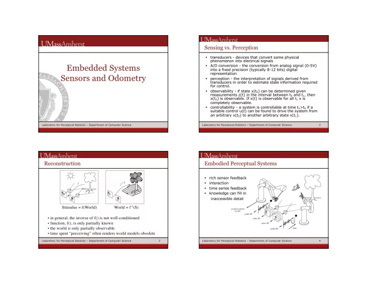
Reconstruction
Stimulus = f(World) World = f-1(S)
- in general, the inverse of f() is not well-conditioned
- function, f(), is only partially known
- the world is only partially observable
- time spent “perceiving” often renders world models obsolete
4 Laboratory for Perceptual Robotics – Department of Computer Science
Embodied Perceptual Systems
§ rich sensor feedback § interaction § time series feedback § knowledge can fill in inaccessible detail