effect of carbon nanotubes on fatigue life of carbon
play

EFFECT OF CARBON NANOTUBES ON FATIGUE LIFE OF CARBON FIBER/EPOXY - PDF document

18 TH INTERNATIONAL CONFERENCE ON COMPOSITE MATERIALS EFFECT OF CARBON NANOTUBES ON FATIGUE LIFE OF CARBON FIBER/EPOXY COMPOSITES L. Gorbatikh, T. Li, N. De Greef*, S.V. Lomov, I. Verpoest Katholieke Universiteit Leuven, Department of Metallurgy


  1. 18 TH INTERNATIONAL CONFERENCE ON COMPOSITE MATERIALS EFFECT OF CARBON NANOTUBES ON FATIGUE LIFE OF CARBON FIBER/EPOXY COMPOSITES L. Gorbatikh, T. Li, N. De Greef*, S.V. Lomov, I. Verpoest Katholieke Universiteit Leuven, Department of Metallurgy and Materials Engineering, Kasteelpark Arenberg 44, B-3001 Heverlee , Belgium � * Corresponding author (Niels.DeGreef@mtm.kuleuven.be) Keywords : carbon nanotubes, fiber-reinforced composites, fatigue, damage development 1 Suppression of damage development for carbon fiber composites falls between two thresholds corresponding to the onset of transverse High performance fiber-reinforced polymer cracks and the appearance of local delaminations, composites (FRCs) possess excellent stiffness and respectively. If the hypothesis about interrelations strength, but their toughness is limited by early between transition thresholds in quasi static tensile damage initiation. Damage in the form of tests and limits of tension-tension fatigue life is transverse cracks can jeopardize reliability of confirmed, then the hindering effect of CNTs on composite parts operating under fatigue loading damage initiation and development on the micro- and its retardation in early stages of damage level may have an important role to play in the development is desirable. In the previous study fatigue properties of these composites. The current [1,2] the authors investigated the effect of carbon work aims to investigate the effect of CNTs on nanotubes (CNTs) on the initiation and tension-tension fatigue life of woven carbon development of damage in a woven carbon fiber/epoxy composites with CNTs introduced in fiber/epoxy composite under quasi-static tensile the matrix. loading. The composite was produced using resin 
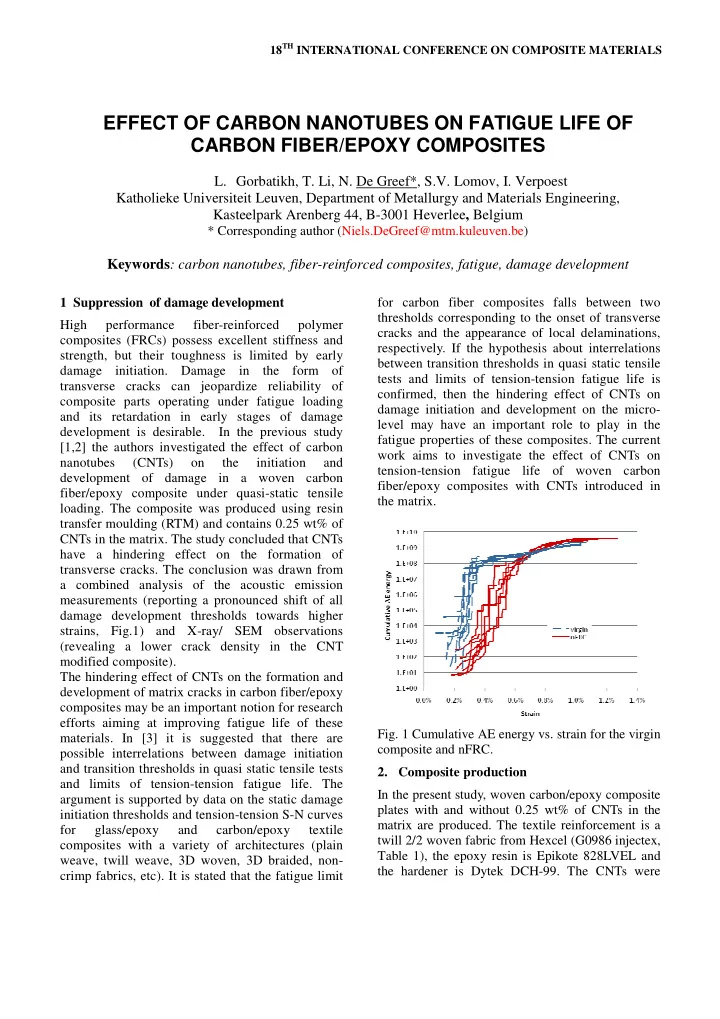
transfer moulding (RTM) and contains 0.25 wt% of CNTs in the matrix. The study concluded that CNTs have a hindering effect on the formation of transverse cracks. The conclusion was drawn from a combined analysis of the acoustic emission measurements (reporting a pronounced shift of all damage development thresholds towards higher strains, Fig.1) and X-ray/ SEM observations (revealing a lower crack density in the CNT modified composite). The hindering effect of CNTs on the formation and development of matrix cracks in carbon fiber/epoxy composites may be an important notion for research efforts aiming at improving fatigue life of these Fig. 1 Cumulative AE energy vs. strain for the virgin materials. In [3] it is suggested that there are composite and nFRC. possible interrelations between damage initiation 2. Composite production and transition thresholds in quasi static tensile tests and limits of tension-tension fatigue life. The In the present study, woven carbon/epoxy composite argument is supported by data on the static damage plates with and without 0.25 wt% of CNTs in the initiation thresholds and tension-tension S-N curves matrix are produced. The textile reinforcement is a for glass/epoxy and carbon/epoxy textile twill 2/2 woven fabric from Hexcel (G0986 injectex, composites with a variety of architectures (plain Table 1), the epoxy resin is Epikote 828LVEL and weave, twill weave, 3D woven, 3D braided, non- the hardener is Dytek DCH-99. The CNTs were crimp fabrics, etc). It is stated that the fatigue limit

  2. produced by Nanocyl and incorporated in a had good impregnation without detected voids or dry areas . Bisphenol-A epoxy resin (EpoCyl NC R128-02). The received master batch epoxy resin contained a 3. Fatigue life results high content of non-functionalized MWCNTs, with The fatigue tests were performed in a load control an average diameter around 9 nm and a length of several microns. mode under constant stress amplitude, assuming the stress ratio R = 0.1 (ratio of the minimum to the Table 1 Twill 2/2 woven carbon fabric maximum stress in the cycle) according to ASTM D3479-36 standard. These tests were carried out Hexcel G0986 injectex both in the fiber and bias directions. The samples Fabric type Twill 2/2 woven failed away from the end tabs (Fig.2). Areal density, g/m2 300 It is found that the number of cycles till failure for Fibers Carbon AS4C the virgin and nano-engineered composite (nFRC) GP Yarns 6K tested in the fiber direction is about the same for the Linear density, tex 400 high stress levels. It is somewhat expected as Picks and ends, yarns/cm 3.5 fatigue properties for low cycle fatigue are dominated by properties of the fibers, and nano- The plates were produced using the resin transfer modification of the matrix has a very limited effect. moulding technique with the processing parameters The number of cycles is markedly increased for low listed in Table 2. stress levels. The reason for this is that the high Table 1 RTM production parameters cycle fatigue behavior is strongly affected by fatigue performance of the resin, and one may expect RTM parameters improvement with nano-modification of the resin. Number of fabric layers 7 The data for the lowest stress levels are presented in Fig. 3 for the fiber and bias directions. The arrows Spacer thickness, mm 2.0 indicate samples that are not broken. Degassing time, min 20 From the stress-strain curves recorded in the fatigue Applied injection vacuum, mbar 10-20 tests in the bias direction (Fig.4), the data show Injection temperature, °C 40 significant hysteresis in each cycle. The consecutive Injection pressure, bar 2 cycles are also shifted, which indicates a progressing Curing temperature, °C 70 permanent elongation of the sample. It is interesting Curing pressure, bar 4 to note that the FRC sample has a larger start strain Curing time, hour 1 in comparison with the strai of the nFRC sample in Post-curing temperature, °C 150 the same cycle. For example, after 72000 cycles, the start strain of the FRC is more than 0.06, but for the Post-curing pressure, bar 4 nFRC it is less than 0.01. This means that after the Post-curing pressure time, hour, 1 same number of cycles, the FRC has a larger The thickness variation and the fiber volume fraction elongation, this was also apperant from the V f of FRCs and nano-engineered fiber reinforced appearance of the failed specimens (Fig. 2). composites (nFRCs) are summarized in Table 3. Table 3 Thickness and V f variation Thickness, mm V f , % (a) Average, std Average, std FRC 2.14 ±0.044 55.3 ±1.1 nFRC 2.06 ±0.087 57.3 ±2.4 (b) The quality control of the composite cross-sections with optical microscopy confirmed that composites Fig. 2 Fracture surfaces after fatigue tests in the (a) fiber direction and (b) bias direction.

  3. EFFECT OF CARBON NANOTUBES ON FATIGUE LIFE OF CARBON FIBER/EPOXY COMPOSITES The X-ray radiography and scanning electron The dispersion of CNTs in the composites is found microscopy were employed to investigate damage to be not homogeneous as shown in Fig. 7. patterns in the tested specimens. These studies Although the resin has been stirred for 10 minutes indicate a significant decrease in the density of during the production, some areas have less CNTs transverse cracks and delaminations in the nano- or no CNTs at all. modified composite even if the latter was subjected In conclusion, the addition of CNTs in the matrix to a higher number of cycles (Fig. 5). It is important improves matrix dominated fatigue properties of to note that the number of cycles for the nFRC is carbon fiber /epoxy composites. about 4 times than that for the FRC. The X-ray study indicates that the crack density in the nFRC is less than that in the FRC. Fig. 6 shows images of samples tested in the bias direction (at 100 MPa). Fig. 3 The tension-tension fatigue data for the virgin (blue) and CNT modified (red) carbon fiber/epoxy composites in the fiber and bias directions, at 500 MPa and 100 MPa load level, respectively. Fig. 4 Stress-strain data from the fatigue test in the bias direction for (a) FRC and (b) nFRC. Fig. 5 X-ray images of the failed virgin sample (~1mln cycles) and the unbroken CNT modified sample (~5 mln cycles) after fatigue tests at 500 MPa in the fiber direction . 3

  4. Fig. 6 X-Ray images of FRC (left) and nFRC (right) samples after fatigue test at 100 MPa Fig. 7 SEM image of the fatigue fracture surfaces of nFRC showing CNTs in the matrix. Acknowledgments [3] SV Lomov, V Carvelli, I Verpoest. Correlations between damage initiation thresholds in textile The work at K.U.Leuven was performed in the composites and fatigue life limits. the Proceedings of scope of the GOA/10/004 project “New model- 10 th the international conference on textile based concepts for nano-engineered polymer composites : Recent advances in textile composites, composites”, funded by the Research Council of edited by Binetruy C. and Boussu F. p. 475-481, 2010. K.U.Leuven. References [1] N. De Greef, L. Gorbatikh, A. Godara, L. Mezzo, S.V. Lomov, I. Verpoest . “ Effect of carbon nanotubes on the damage development in carbon fiber/epoxy composites”, Carbon, 2011 (under review) [2] N. De Greef, L. Gorbatikh, S. V.Lomov, I. Verpoest. “Damage development in woven carbon fiber/epoxy composites modified with carbon nanotubes under tension in the bias direction”, Composites: Part A, 2011 (under review)

Download Presentation
Download Policy: The content available on the website is offered to you 'AS IS' for your personal information and use only. It cannot be commercialized, licensed, or distributed on other websites without prior consent from the author. To download a presentation, simply click this link. If you encounter any difficulties during the download process, it's possible that the publisher has removed the file from their server.

Recommend


More recommend