SLIDE 1
EDA421/DIT171 - Parallel and Distributed Real-Time Systems, Chalmers/GU, 2010/2011 Lecture #10
Updated November 21, 2010
1
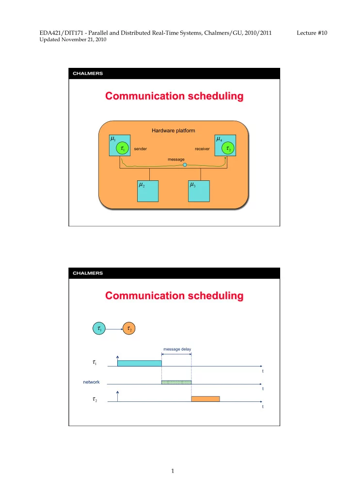
Hardware platform
message sender receiver message delay
T1 T2
t t
network
t
SLIDE 2
EDA421/DIT171 - Parallel and Distributed Real-Time Systems, Chalmers/GU, 2010/2011 Lecture #10
Updated November 21, 2010
2
SLIDE 3
EDA421/DIT171 - Parallel and Distributed Real-Time Systems, Chalmers/GU, 2010/2011 Lecture #10
Updated November 21, 2010
3 and – Communication distance (m) – Signal propagation velocity (m/s) – Message length (bits) – Data rate (bits/s)
SLIDE 4
EDA421/DIT171 - Parallel and Distributed Real-Time Systems, Chalmers/GU, 2010/2011 Lecture #10
Updated November 21, 2010
4
SLIDE 5
EDA421/DIT171 - Parallel and Distributed Real-Time Systems, Chalmers/GU, 2010/2011 Lecture #10
Updated November 21, 2010
5
SLIDE 6
EDA421/DIT171 - Parallel and Distributed Real-Time Systems, Chalmers/GU, 2010/2011 Lecture #10
Updated November 21, 2010
6
release jitter
queuing delay transmission delay notification delay T1 T2
t t
network
t
SLIDE 7
EDA421/DIT171 - Parallel and Distributed Real-Time Systems, Chalmers/GU, 2010/2011 Lecture #10
Updated November 21, 2010
7
T1 T2
t t
network
t
dedicated time slot
SLIDE 8
EDA421/DIT171 - Parallel and Distributed Real-Time Systems, Chalmers/GU, 2010/2011 Lecture #10
Updated November 21, 2010
8
SLIDE 9 EDA421/DIT171 - Parallel and Distributed Real-Time Systems, Chalmers/GU, 2010/2011 Lecture #10
Updated November 21, 2010
9
– Based on the CAN protocol – Bus topology – Media: twisted pair – 1Mbit/s
Node 2 Node 7 Node 1 Node 4 Node 3 Node 6 Node 5 A S S S
CPU/ mem/CC Node
A second controller is required to implement the redundant bus
Basic cycle Basic cycle 1 Basic cycle 2 Basic cycle 3
Transmission Columns
t
”Exclusive” – guaranteed service ”Arbitration” – guaranteed service (high ID), best effort (low ID) ”Reserved” – for future expansion...
Time is global and measured in network time units (NTU’s)
SLIDE 10 EDA421/DIT171 - Parallel and Distributed Real-Time Systems, Chalmers/GU, 2010/2011 Lecture #10
Updated November 21, 2010
10
Node 1 Node 4 Node 3 Node 2 Node 6 Node 5
A B
Node 1 Node 2 Node 3 Node 4 Node 5 Node 6
– Double channels (one redundant). Bus topology or ”star” (optical) – Media: twisted pair, fibre – 10 Mbit/s for each channel
A S S S
CPU/ mem/CC Node
A network is built on either twin buses or twin stars. Non-periodic messages have to be fitted into static slots by the application
”TDMA-round”
”message slots” t All communication is statically scheduled
Guaranteed service
SLIDE 11 EDA421/DIT171 - Parallel and Distributed Real-Time Systems, Chalmers/GU, 2010/2011 Lecture #10
Updated November 21, 2010
11
Node 1 Node 3 Node 2 Node 6 Node 5
A B
Node 7
Node 4
Redundant channel can be used for an alternative schedule
A S S S
CPU/ mem/CC Node
– Double channels, bus or star (even mixed). – Media: twisted pair, fibre – 10 Mbit/s for each channel
Guaranteed periodical Guaranteed periodical/ aperiodical ”Best-effort” aperiodical 63 62 3 2 1 Network Idle Time Symbol window Static segment (m slots) Dynamic segment (n mini-slots)
Max 64 nodes on a Flexray network.
”Static segment” (compare w/ TTCAN ”Exclusive”) – guaranteed service ”Dynamic segment” (compare w/ TTCAN ”Arbitration”) – guaranteed service (high ID), ”best effort” (low ID)
SLIDE 12
EDA421/DIT171 - Parallel and Distributed Real-Time Systems, Chalmers/GU, 2010/2011 Lecture #10
Updated November 21, 2010
12
SLIDE 13
EDA421/DIT171 - Parallel and Distributed Real-Time Systems, Chalmers/GU, 2010/2011 Lecture #10
Updated November 21, 2010
13
A necessary feasibility test: A sufficient feasibility test:
constantly rotating token
SLIDE 14 EDA421/DIT171 - Parallel and Distributed Real-Time Systems, Chalmers/GU, 2010/2011 Lecture #10
Updated November 21, 2010
14
SD AC ED ED FS addresses packet data error control Message frame format SD AC ED Token format P P P T M R R R P P P R R R AC AC
PPP: priority field RRR: reservation field
- 1. Each node examines RRR of a busy token as it passes and
inserts the priority of its pending message only if it is greater than the priority currently in RRR.
- 2. A node does not grab a “free” token unless the priority of its
pending message is at least as high as the priority in PPP. Then the token status is changed to “busy”.
- 3. A transmitting node appends its pending message after the
“busy” token and sets RRR appropriately.
- 4. A transmitting node waits until it receives back the “busy”
token before releasing the next “free” token with PPP set to the (possibly) updated RRR.
SLIDE 15
EDA421/DIT171 - Parallel and Distributed Real-Time Systems, Chalmers/GU, 2010/2011 Lecture #10
Updated November 21, 2010
15
A sufficient and necessary feasibility test:
– Capture token when node has highest-priority message pending – Transmit message – Transmit subsequent free token
SLIDE 16
EDA421/DIT171 - Parallel and Distributed Real-Time Systems, Chalmers/GU, 2010/2011 Lecture #10
Updated November 21, 2010
16
collision-detect broadcast bus
SLIDE 17
EDA421/DIT171 - Parallel and Distributed Real-Time Systems, Chalmers/GU, 2010/2011 Lecture #10
Updated November 21, 2010
17
11-bit identifier 0 - 8 bytes of message data error control SOF Ack EOF control
SLIDE 18 EDA421/DIT171 - Parallel and Distributed Real-Time Systems, Chalmers/GU, 2010/2011 Lecture #10
Updated November 21, 2010
18
- 1. Each node with a pending message waits until bus is idle.
- 2. The node begins transmitting the highest-priority message
pending on the node. Identifier is transmitted first, in the order
- f most-significant bit to least-significant bit.
- 3. If a node transmits a recessive bit (’1’) but sees a dominant
bit (’0’) on the bus, then it stops transmitting since it is not transmitting the highest-priority message in the system.
- 4. The node that transmits the last bit of its identifier without
detecting a bus inconsistency has the highest priority and can start transmitting the body of the message.