
SLIDE 1
1
Mor M. Peretz, Switch-Mode Power Supplies
[7-1]
Drivers
- What is a driver
- MOSFET capacitances
- Diver operation
- Gate capacitance
- Gate drive calculation
- Driver types
- High-side driver
- Isolation
- Optocoupler
- Boot-strap supply
Mor M. Peretz, Switch-Mode Power Supplies
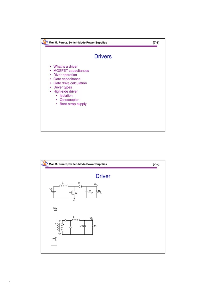
[7-2]