Distributed Systems - I Resource sharing sharing and printing - - PDF document

distributed systems i
SMART_READER_LITE
LIVE PREVIEW

Distributed Systems - I Resource sharing sharing and printing - - PDF document

CSE 421/521 - Operating Systems Motivation Fall 2011 Distributed system is collection of loosely coupled processors that do not share memory Lecture - XXIII interconnected by a communications network Reasons for distributed


slide-1
SLIDE 1

1

CSE 421/521 - Operating Systems Fall 2011

Tevfik Koşar

University at Buffalo

November 22nd, 2011

Lecture - XXIII

Distributed Systems - I

Motivation

  • Distributed system is collection of loosely coupled processors that

– do not share memory – interconnected by a communications network

  • Reasons for distributed systems

– Resource sharing

  • sharing and printing files at remote sites
  • processing information in a distributed database
  • using remote specialized hardware devices

– Computation speedup – load sharing – Reliability – detect and recover from site failure, function transfer, reintegrate failed site – Communication – message passing

Distributed-Operating Systems

  • Users not aware of multiplicity of machines

– Access to remote resources similar to access to local resources

  • Data Migration – transfer data by transferring

entire file, or transferring only those portions of the file necessary for the immediate task

  • Computation Migration – transfer the

computation, rather than the data, across the system

Distributed-Operating Systems (Cont.)

  • Process Migration – execute an entire process, or parts
  • f it, at different sites

– Load balancing – distribute processes across network to even the workload – Computation speedup – subprocesses can run concurrently on different sites – Hardware preference – process execution may require specialized processor – Software preference – required software may be available at

  • nly a particular site

– Data access – run process remotely, rather than transfer all data locally

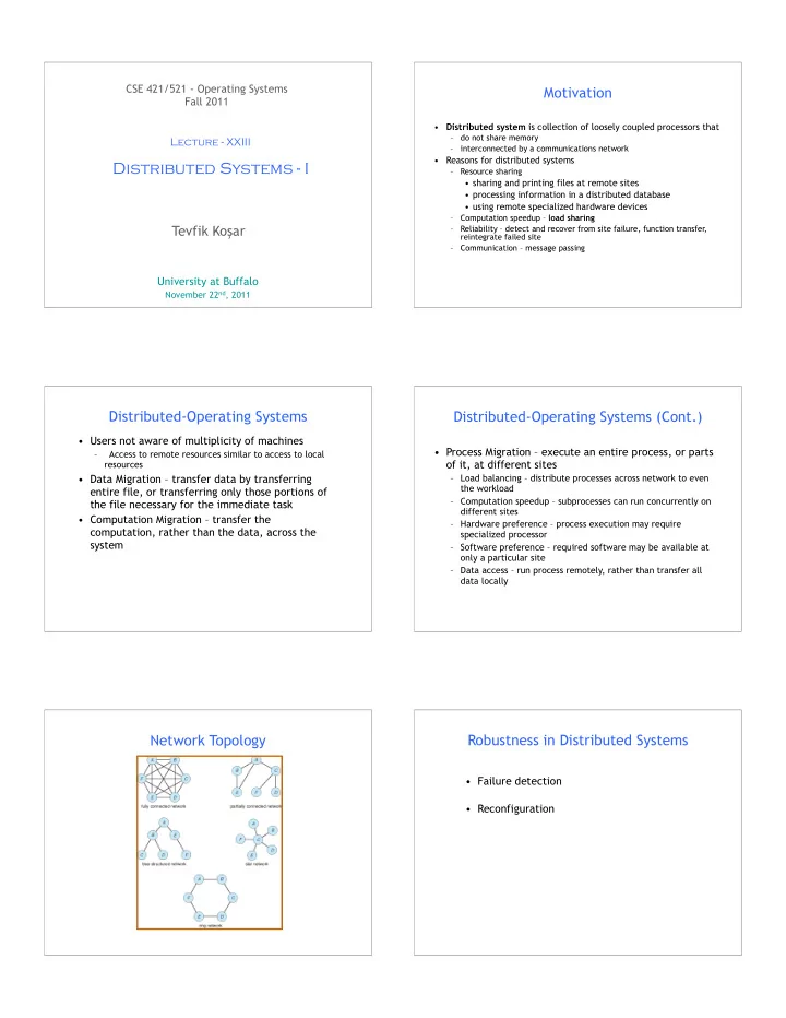
Network Topology Robustness in Distributed Systems

  • Failure detection
  • Reconfiguration
slide-2
SLIDE 2

Failure Detection

  • Detecting hardware failure is difficult
  • To detect a link failure, a handshaking protocol can be

used

  • Assume Site A and Site B have established a link

– At fixed intervals, each site will exchange an I-am-up message indicating that they are up and running

  • If Site A does not receive a message within the fixed

interval, it assumes either (a) the other site is not up or (b) the message was lost

  • Site A can now send an Are-you-up? message to Site B
  • If Site A does not receive a reply, it can repeat the message
  • r try an alternate route to Site B

Failure Detection (cont)

  • If Site A does not ultimately receive a reply from Site B,

it concludes some type of failure has occurred

  • Types of failures:
  • Site B is down
  • The direct link between A and B is down
  • The alternate link from A to B is down
  • The message has been lost
  • However, Site A cannot determine exactly why the

failure has occurred

Reconfiguration

  • When Site A determines a failure has occurred, it must

reconfigure the system:

  • 1. If the link from A to B has failed, this must be

broadcast to every site in the system

  • 2. If a site has failed, every other site must also be

notified indicating that the services offered by the failed site are no longer available

  • When the link or the site becomes available again, this

information must again be broadcast to all other sites

Distributed Coordination

  • Ordering events and achieving synchronization in

centralized systems is easier.

– We can use common clock and memory

  • What about distributed systems?

– No common clock or memory – happened-before relationship provides partial ordering – How to provide total ordering?

Event Ordering

  • Happened-before relation (denoted by →)

– If A and B are events in the same process (assuming sequential processes), and A was executed before B, then A → B – If A is the event of sending a message by one process and B is the event of receiving that message by another process, then A → B – If A → B and B → C then A → C – If two events A and B are not related by the → relation, then these events are executed concurrently.

Relative Time for Three Concurrent Processes

Which events are concurrent and which ones are ordered?

slide-3
SLIDE 3

Exercise

Which of the following event orderings are true? (a) p0 --> p3 : (b) p1 --> q3 : (c) q0 --> p3 : (d) r0 --> p4 : (e) p0 --> r4 : Which of the following statements are true? (a) p2 and q2 are concurrent processes. (b) q1 and r1 are concurrent processes. (c) p0 and q3 are concurrent processes. (d) r0 and p0 are concurrent processes. (e) r0 and p4 are concurrent processes.

13

Implementation of →

  • Associate a timestamp with each system event

– Require that for every pair of events A and B, if A → B, then the timestamp

  • f A is less than the timestamp of B
  • Within each process Pi, define a logical clock

– The logical clock can be implemented as a simple counter that is incremented between any two successive events executed within a process

  • Logical clock is monotonically increasing
  • A process advances its logical clock when it receives a message whose

timestamp is greater than the current value of its logical clock

– Assume A sends a message to B, LC1(A)=200, LC2(B)=195 --> LC2(B)=201

  • If the timestamps of two events A and B are the same, then the events

are concurrent

– We may use the process identity numbers to break ties and to create a total ordering

Distributed Mutual Exclusion (DME)

  • Assumptions

– The system consists of n processes; each process Pi resides at a different processor – Each process has a critical section that requires mutual exclusion

  • Requirement

– If Pi is executing in its critical section, then no other process Pj is executing in its critical section

  • We present two algorithms to ensure the mutual

exclusion execution of processes in their critical sections

DME: Centralized Approach

  • One of the processes in the system is chosen to coordinate the

entry to the critical section

  • A process that wants to enter its critical section sends a

request message to the coordinator

  • The coordinator decides which process can enter the critical

section next, and its sends that process a reply message

  • When the process receives a reply message from the

coordinator, it enters its critical section

  • After exiting its critical section, the process sends a release

message to the coordinator and proceeds with its execution

  • This scheme requires three messages per critical-section

entry:

– request – reply – release

DME: Fully Distributed Approach

  • When process Pi wants to enter its critical section, it

generates a new timestamp, TS, and sends the message request (Pi, TS) to all processes in the system

  • When process Pj receives a request message, it may

reply immediately or it may defer sending a reply back

  • When process Pi receives a reply message from all other

processes in the system, it can enter its critical section

  • After exiting its critical section, the process sends reply

messages to all its deferred requests

DME: Fully Distributed Approach (Cont.)

  • The decision whether process Pj replies immediately to a

request(Pi, TS) message or defers its reply is based on three factors:

– If Pj is in its critical section, then it defers its reply to Pi – If Pj does not want to enter its critical section, then it sends a reply immediately to Pi – If Pj wants to enter its critical section but has not yet entered it, then it compares its own request timestamp with the timestamp TS

  • If its own request timestamp is greater than TS, then it

sends a reply immediately to Pi (Pi asked first)

  • Otherwise, the reply is deferred

– Example: P1 sends a request to P2 and P3 (timestamp=10) P3 sends a request to P1 and P2 (timestamp=4)

slide-4
SLIDE 4

Undesirable Consequences

  • The processes need to know the identity of all other

processes in the system, which makes the dynamic addition and removal of processes more complex

  • If one of the processes fails, then the entire scheme

collapses

– This can be dealt with by continuously monitoring the state of all the processes in the system, and notifying all processes if a process fails