development of the method for interaction between shock
play

DEVELOPMENT OF THE METHOD FOR INTERACTION BETWEEN SHOCK WAVE - PDF document

DEVELOPMENT OF THE METHOD FOR INTERACTION BETWEEN SHOCK WAVE AND FLAME M.Bliznetsov 1 , V.Dudin 1 , S.Gerasimov 1 , L.Houas 3 , G.Jourdan 3 , A.Logvinov 1,2 , E.Meshkov 1,2 , Yu.Vlasov 1 1 Russian Federal Nuclear Center Institute of


  1. DEVELOPMENT OF THE METHOD FOR INTERACTION BETWEEN SHOCK WAVE AND FLAME M.Bliznetsov 1 , V.Dudin 1 , S.Gerasimov 1 , L.Houas 3 , G.Jourdan 3 , A.Logvinov 1,2 , E.Meshkov 1,2 , Yu.Vlasov 1 1 Russian Federal Nuclear Center – Institute of Experimental Physics (VNIIEF), 607190, Sarov,Russia 2 Sarov Physics Technical Institute, 607190, Sarov, Russia 3 IUSTI/CNRS UMR 6595, Universite de Provence, Technopole de Chateau-Gombert, 13013, Marseille, France 1. Introduction. Wild fires are disastrous events damaging the environment. Numerous examples show that extinguishing the wild fires is a hard line, which does not ever finish successfully. Let us remember, for example, the fire in the Los Alamos region in spring, 2000. There is a method of extinguishing the wild fires by means of exploding of longitudinal charge located before the flame front [1,2]. Here, there is observed the amplifying of the shock wave after it passing through the flame zone. The effectiveness of the method was experimentally demonstrated [3]. However, it is not put into practice. According to the authors’ hypothesis [3] this extinguishing is due to blowing a flame off by a shock. Amplifying the shock is considered in terms of additional explosion of a mixture consisting of air and pyrolysis products (PP) from crown fragments (pine needles, small branches, and leaves). This additional explosion is supposed to follow a shock from initial explosion. There is another hypothesis [4], which considers the process is due to growing the hydrodynamic instabilities. On explosion of a cylindrical longitudinal charge, an expanding non-steady shock is generated. The substance accelerates on the shock wave front, and, then decelerates. When the shock wave passes through the flame front, this corresponds to its propagation from a substance with a more high density (PP-air mixture) into another of lower one (flame). As a result, we have conditions for occurrence of instability induced by the shock wave [5,6], and then, the conditions of Rayleigh-Taylor instability arise for the flow behind the front of shock wave because the acceleration directs from light to heavy substance [7,8]. Thus, the instability of flame front grows, and an intense mixing between flame and PP-air mixture should arise, so it should effect the sharp combustion of this mixture. A rapid (or possibly, explosive) combustion of the mixture should result in generation of a compression wave (or series of compression waves) overrunning and amplifying the shock wave generated by the charge explosion. Experimental research with a real wild fire is rather complex, dangerous, and expensive. That is why the new methods for study the interaction between non-steady shock with a flame front in cases close to a crown forest fires are of actual interest. The results obtained at developing such method are presented below. The most complex problem here is to create a model even qualitatively related to peculiarities of crown fire propagation: • generation of gaseous explosive mixtures before flame front due to its high temperature • high rate for the flame front propagation For study the interaction between non-steady shock with a flame front we suggest a spatial model consisting of parallel (or diverging from a point) threads or rods along which an inflammable substance able to be fume before a flame front is distributed. A non-steady shock could be generated towards the flame front propagating through the model; so, one can observe the process of the shock-flame interaction. The means for generating the non-steady shock could be different for different scales: • electrical explosion of a wire tightened before the lame front; • shock tube with compressed gas or gaseous explosive mixture as a driver [9]; • explosion of a longitudinal HE (for example, detonation flex). 2. Experimental research for the spatial thread model. 
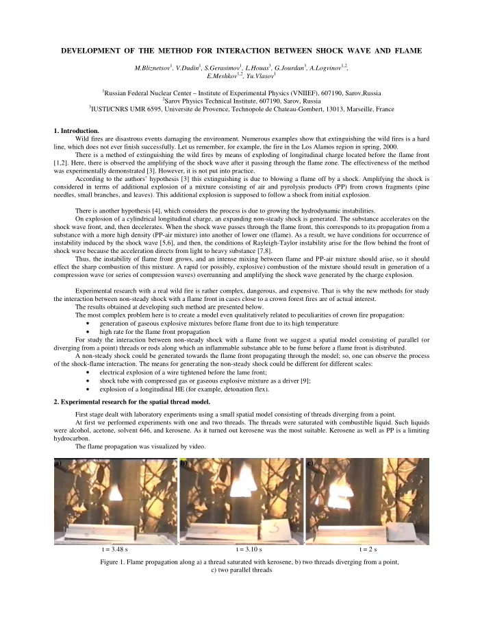
First stage dealt with laboratory experiments using a small spatial model consisting of threads diverging from a point. At first we performed experiments with one and two threads. The threads were saturated with combustible liquid. Such liquids were alcohol, acetone, solvent 646, and kerosene. As it turned out kerosene was the most suitable. Kerosene as well as PP is a limiting hydrocarbon. The flame propagation was visualized by video. a) b) c) t = 3.48 s t = 3.10 s t = 2 s Figure 1. Flame propagation along a) a thread saturated with kerosene, b) two threads diverging from a point, c) two parallel threads

  2. Figure 1 presents the frames of the flame propagation a) along a thread, b) along two threads diverging from a point, and c) along two parallel threads. The frames show that in b) case the upper flame overruns the low – it was due to the dependence of flame rate on slope tangent. We performed a series of tests varying the slope tangent. The results obtained were handled (Figure 2). Ought to note the linear character for the dependence. �� α = 4 o 4’ 12 ��� ���� �� α = -7 o 1’ ��� �� ��� 11 �� α = 10 o 9’ ��� ����� �� 10 α = -15 o 6’ U, cm/c �� ��� �� ���� 9 α = 16 o 1’ �� � ��� ����� � �� 8 �� 7 �� � 6 � -20 -15 -10 -5 0 5 10 15 20 � � � � � � � α , grad ��� Figure 3. Dependence of rate of flame propagation U along a Figure 2. Dependence in time t of the flame front propagation S thread against its slope tangent α . along a thread on its slope tangent α . The angle is counted from skyline, positive direction at propagation from below. The measured rate of flame propagation for the tests is presented in Figure 3. Figure 4 shows the frames for flame propagation in a model consisting of 25 threads diverging from a point. The ends of threads were fixed in knots of a grid (5 × 5) with a cell of 2 cm. The threads were saturated with kerosene. Figure 5 shows the results of measurements for this model. It should be noted that at recording the process from side one could find a) a weak acceleration of the flame front and b) overrunning for the second thread from the top (Figure 4,a a frame at 3.15 s.) but not for the upper. Simultaneously, at recording from above one could observe the overrunning in the middle region (Figure 4,b). These effects could be related to the heating of the threads before the flame front and evaporating of the combustible liquid from the threads. A more intensive heating of the threads should be realized in the middle region of the front. Due to the more intensive heating a more intensive evaporation of the combustible liquid is realized that corresponds to a more rapid propagation of the flame front. These effects are weakly found here owing to the small sizes of the model; apparently, increasing the scale of these effects should follow increasing the model sizes. 3. Shock wave and flame interaction. Preliminary tests. We have performed a few preliminary tests for the shock wave and flame interaction. There were two types of the tests: 1. The shock wave was induced by electrical explosion of a thin metal wire (nickel-chrome, 0.05mm) through which there was realized a discharge from a capacity of 0.1mcF at 60kV. It was followed by a cylindrical shock wave. The shadow pattern of the interaction between the shock wave and the flame propagating along a thread saturated with kerosene was visualized with a high-speed camera. The thread and wire were located in the same plane; the axis of the thread was normal to the wire’s. The frames for the interaction process are presented in Figure 6. One can find the following stages of the process: • some displacement of the flame under shock wave • generation of a part of the shock wave passed through the flame and overrunning the main part of the front (ShW 1 ) • growth of perturbations on the initially smooth, laminar flame front with its further turbulence. In this test the flame was more probably extinguished due to blowing it off. But it is a fact that the flame being initially laminar with a rather smooth front got unstable and turbulent. 2. In test (Figure 8) the shock wave was generated through detonation of a layer (8 × 8 × 2 cm) of gaseous explosive mixture of acetylene and oxygen. Initially, the mixture filled the volume of a shock tube [9] with rigid lateral and back walls; the output window was closed with a thin mylar film of 0.9mm - thickness. In this case the flame was generated on a spatial model with 25 parallel threads saturated with kerosene. Figure 8 shows the frames of shadow pattern for the interaction process. The shock wave was stronger (2-3 Mach) in this case. The flame was extinguished with the wave. There were observed both the perturbation growth and sufficient displacement of the flame under the wave.

  3. b) a) t = 0 s. t=0 s t = 1.14 s t = 2.15 s t = 3.15 s t = 5 s t = 4 s Figure 4. Flame propagation along spatial model consisting of 5 × 5 threads diverging from a point a) side view, b) from above view (test N16 and 18) 45 S1 40 S2 35 S3 S4 30 S5 25 S,cm 20 15 10 5 0 0 1 2 3 4 5 6 t,s Figure 5. Dependence of flame propagation S along diverging threads saturated with kerosene on time t

Download Presentation
Download Policy: The content available on the website is offered to you 'AS IS' for your personal information and use only. It cannot be commercialized, licensed, or distributed on other websites without prior consent from the author. To download a presentation, simply click this link. If you encounter any difficulties during the download process, it's possible that the publisher has removed the file from their server.

Recommend


More recommend