DESY Experiences in Hydroforming of Elliptical RF Cavities W. - - PowerPoint PPT Presentation

desy experiences in hydroforming of elliptical rf cavities
SMART_READER_LITE
LIVE PREVIEW

DESY Experiences in Hydroforming of Elliptical RF Cavities W. - - PowerPoint PPT Presentation

DESY Experiences in Hydroforming of Elliptical RF Cavities W. Singer Introduction Hydroforming technique (necking, expansion) Nb tubes for hydroforming Examples of RF performance W. Singer. DESY Experiences in Hydroforming.


slide-1
SLIDE 1
  • W. Singer. DESY Experiences in Hydroforming. Hydroforming Workshop, September 1, 2010, FNAL, USA

DESY Experiences in Hydroforming

  • f Elliptical RF Cavities
  • W. Singer
  • Introduction
  • Hydroforming technique (necking, expansion)
  • Nb tubes for hydroforming
  • Examples of RF performance
slide-2
SLIDE 2
  • W. Singer. DESY Experiences in Hydroforming. Hydroforming Workshop, September 1, 2010, FNAL, USA

Introduction

Advantages of seamless cavity fabrication

  • no RRR degradation in the welding seam, in the heat affected zone

HAZ and in the weld overlapping

  • no risk of equator weld contamination due to not sufficiently clean

preparation for welding

  • no problem with pits in the HAZ, that are intensively in discussion

last time

  • lower cost of fabrication can be expected, especially for large series.
  • less scattering in performance statistic of seamless cavity compare to

welded cavities is to expect .

slide-3
SLIDE 3
  • W. Singer. DESY Experiences in Hydroforming. Hydroforming Workshop, September 1, 2010, FNAL, USA

Hydroforming consists of two steps: a) reduction of diameters at ends of tubes and iris areas (necking) b) tube expansion at the equator

Hydroforming technique

slide-4
SLIDE 4
  • W. Singer. DESY Experiences in Hydroforming. Hydroforming Workshop, September 1, 2010, FNAL, USA

Several necking methods were check out before the current necking procedure was established

  • spinning
  • necking by profile ring
  • hydraulic necking
  • electromagnetic strike necking,
  • verjungen (diameter reduction by push the tube end through

the set of rings of smaller diameter)

  • rotary swaging (rundkneten)

Step 1: necking

Principle

  • f rotary

swaging

slide-5
SLIDE 5
  • W. Singer. DESY Experiences in Hydroforming. Hydroforming Workshop, September 1, 2010, FNAL, USA

Not uniform necking at the iris area of tube end done at company HTI by spinning ( hole appeared during centrifugal barrel polishing).

Step 1: necking

  • necking by spinning

KEK necking machine (successful on Cu-tubes)

In principle it works

slide-6
SLIDE 6
  • W. Singer. DESY Experiences in Hydroforming. Hydroforming Workshop, September 1, 2010, FNAL, USA

Principle of diameter reduction in the tube end and iris area

Step 1: necking (by profile ring)

Improvement of the necking procedure and development of DESY necking equipment provided the success (combination of radial and axial movement ) Principle of DESY necking equipment

slide-7
SLIDE 7
  • W. Singer. DESY Experiences in Hydroforming. Hydroforming Workshop, September 1, 2010, FNAL, USA

Reduction mechanism.

Seamless technique by hydroforming: step 1- necking

DESY Necking machine: new PC controlled necking procedure Tubes after reduction in the iris areas DESY developed necking equipment (by profile ring)

Step 1: necking (by profile ring)

slide-8
SLIDE 8
  • W. Singer. DESY Experiences in Hydroforming. Hydroforming Workshop, September 1, 2010, FNAL, USA

Conclusion to necking:

  • spinning: works (essential wall thickness reduction close to

iris, probably this can be improved by parameter optimization)

  • necking by profile ring: works (best results)
  • hydraulic necking: does not work (not round shape)
  • electromagnetic strike necking: works for Cu, can work on Nb
  • nly for bimetallic NbCu tubes (resistance of Nb is to high ),

the shape is not sufficiently under control due to single strike

  • verjungen: works only for single cells (time consuming due to

many rings, not optimal shape of the necking)

  • rotary swaging (rundkneten): works (damaging of the

surface, significant work hardening)

slide-9
SLIDE 9
  • W. Singer. DESY Experiences in Hydroforming. Hydroforming Workshop, September 1, 2010, FNAL, USA

Dependence of the elongation on temperature. It make sense to perform hydroforming of niobium at room temperatures

Step 2: Expansion (Hydroforming)

First question. Hydroforming conditions ,parameters? Is the room temperature appropriate for hydroforming? Yes

DESY data

slide-10
SLIDE 10
  • W. Singer. DESY Experiences in Hydroforming. Hydroforming Workshop, September 1, 2010, FNAL, USA

Dependence

  • f

maximum elongation of niobium versus strain rate (H, M, S different literature data). Correct strain rate should be chosen for hydroforming Chosen strain rate is between 0.01 sec-1 and 0.001 sec-1

1

sec ,

∂ = t ε ε

Strain rate Compilations of C. Antoine

How fast to perform the deformation (hydroforming)?

slide-11
SLIDE 11
  • W. Singer. DESY Experiences in Hydroforming. Hydroforming Workshop, September 1, 2010, FNAL, USA

50 100 150 200 250 0,00 0,20 0,40 0,60 0,80

Epsilon Sigma, N/mm2

Heraeus Tube7. Paralel to axis, contin. Heraeus Tube7. Circum ferential, contin. Heraeus Tube7. Paralel to axis, stepw ise Heraeus Tube7. Circum ferential, stepw ise

Comparison of the tensile test in continues and pulse regime The strain before necking can be increased by using a periodic stress fluctuation (pulse regime). Probably the pull-release regime of the deformation artificially increases the work-hardening of Nb in low-yield strength regions and therefore shift the break to higher elongations.

Pulsing of the pressure during hydroforming helps

slide-12
SLIDE 12
  • W. Singer. DESY Experiences in Hydroforming. Hydroforming Workshop, September 1, 2010, FNAL, USA

DESY hydroforming machine DESY hydroforming machine

  • Designed and build in

Russia (INR, Troitsk)

  • Equipped with

hydraulic systems and software at DESY

  • From dimension is in

position to produce only units of 3 cells

Fixed Matrix Movable Matrix Tube Pcyl sensor Lsensor Oil Hydr system Water Hydr. system Rsensor Ptube sensor

Principle of hydroforming

slide-13
SLIDE 13
  • W. Singer. DESY Experiences in Hydroforming. Hydroforming Workshop, September 1, 2010, FNAL, USA

1 0 0 .0 0 0 .0 0 2 0 .0 0 4 0 .0 0 6 0 .0 0 8 0 .0 0 2 5 3 6 1 2 0 0 4 0 0 6 0 0 8 0 0 1 0 0 0 1 2 0 0 1 4 0 0 1 6 0 0 1 8 0 0 2 0 0 0 2 2 0 0 2 4 0 0 0 . e n d 1 0 0 0 .5 0 2 8 .5 7 b e g 3 9 9 .3 7 1 8 .2 7

gr1

6 5 .0 4 1 .7 4 5 .0 4 7 .5 5 0 .0 5 2 .5 5 5 .0 5 7 .5 6 0 .0 6 2 .5 2 5 .8

  • 0 .1

2 .0 4 .0 6 .0 8 .0 1 0 .0 1 2 .0 1 4 .0 1 6 .0 1 8 .0 2 0 .0 2 2 .0 2 4 .0 m e a s c a lc u C u r 1 1 .6 9 5 0 .5 4

gr2 Init. Load Save Zero Stop Reset Cut Load Dcalc. Show data Save Dcalc.

0.5

P in tube

8Feb2000

Date

2:20

Time

D :\ 1 c e ll h yd ro fo rm in g \ D a ta \ N io b iu m D 8 3 m m P r1 .sto

Path Niobium 137*83.0*2.6mm. L0=51.6. Drossel=300, kran on -8, kran off 135. Niobium tube Pr1. During of hydroforming (18-6mm of length) the shape was conical, dD=5mm). Smooth surface, inside and outside. Calibrated at 560bar. Thickness at equator =2.2mm.

C o m m e n ta ry

P in cylinder y1 Length x2 Radius y2

25.76

Length, mm

0 .8 4 .3 2 5 .8 4 1 .7 3 .1 2 .8 4 .6 2 5 .8 4 1 .7 3 .1

Data PROCESS START

5 2 2 6 6 8 t0 1 4 .9 P ze ro 7 2 .1 6 L ze ro 2 4 .7 0 6 5 .0 0 2 4 .1 7 7 0 .5 0 2 3 .6 5 7 5 .5 0 2 3 .1 2 8 3 .5 0 2 2 .0 7 9 0 .0 0 2 1 .0 2 9 7 .5 0 1 8 .9 2 0 1 .5 0 1 6 .8 2 0 4 .0 0 1 4 .7 1 0 6 .5 0 1 2 .6 1 0 7 .0 0 1 0 .5 1 0 6 .0 0 8 .4 1 0 5 .0 0 6 .3 1 0 3 .0 0 4 .2 0 0 1 .0 0 2 .1 0 9 9 .0 0 0 .0 0 0 .0 0 0 .0 0 0 .0 0 0 .0 0 0 .0 0 2 5 .7 5 4 2 .0 0 2 5 .2 2 5 6 .5 0 D c a lc

41.70

Radius, mm

1 0 7 .8 0 .0 2 0 .0 4 0 .0 6 0 .0 8 0 .0 1 0 0 .0 2 5 .8

  • 0 .1

2 .0 4 .0 6 .0 8 .0 1 0 .0 1 2 .0 1 4 .0 1 6 .0 1 8 .0 2 0 .0 2 2 .0 2 4 .0 m e a s c a lc u C u r 1 8 .9 2 9 7 .5 0

gr3 P in tube y3 Length x3

41.70

R 1

41.70

R 2

0.00

d R

93.6

Pstab

0.10

dL

25.66

L teor

4.4

Pcylinder

  • 1 9 .6

P c ylze ro

0.80 Pscale

170

P tu b e m a x

130

P c yl m a x 4 1 .7 5 R te o r 0 .9 4

K Pstart

0 .9 9 K P sta b 5 0 0 0 T p a u se , m se c 0 .0 d P c o r.% T im e P tu b e L , m m R ,m m P c yl
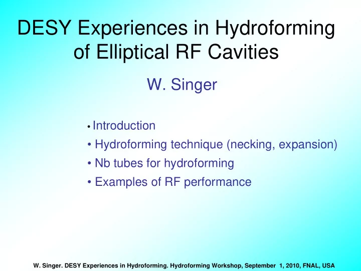
FEM Simulation

  • f the

hydroforming

Pressure-axial displacement Radius-axial displacement

PC control allows reproducibly repeat the forming parameters

Front panel of the software for hydroforming - machine

slide-14
SLIDE 14
  • W. Singer. DESY Experiences in Hydroforming. Hydroforming Workshop, September 1, 2010, FNAL, USA

Hydroforming of cells can be done or as three cells simultaneously or cell by cell (hydroforming of the 9-cells from one tube piece can be done on the same way) All steps of hydroforming optimized and checked on the Cu dummies

slide-15
SLIDE 15
  • W. Singer. DESY Experiences in Hydroforming. Hydroforming Workshop, September 1, 2010, FNAL, USA

Synchronization mechanism for multi cell fabrication by hydroforming Some ideas contributed to hydroforming success Nonsymmetrical mould for hydroforming

Fixed Matrix Movable Matrix Tube Pcyl sensor Lsensor Oil Hydr system Water Hydr. system Rsensor Ptube sensor

Developed ideas summarized in the patent. W.Singer, I.Jelezov; No. 10 2007 037 835 ; 18 September 2008

slide-16
SLIDE 16
  • W. Singer. DESY Experiences in Hydroforming. Hydroforming Workshop, September 1, 2010, FNAL, USA

Fabrication steps of 9 cell cavity by hydroforming as option 3x3

slide-17
SLIDE 17
  • W. Singer. DESY Experiences in Hydroforming. Hydroforming Workshop, September 1, 2010, FNAL, USA

Z145: 9-cell as 3x3 cell cavity hydroformed at DESY, completed at E.ZANON (reached ca. 30 MV/m). Two new 9-cell cavities are currently in completing at E.ZANON

slide-18
SLIDE 18
  • W. Singer. DESY Experiences in Hydroforming. Hydroforming Workshop, September 1, 2010, FNAL, USA

Conclusion to hydroformimng

  • Hydroformig of 9-cell cavity from one tube-piece is feasible
  • Dimensions of a new machine have to be foreseen for that.
  • DESY machine is a laboratory equipment. For industrial

equipment more moulds (intermediate constraints), less sensors for parameter measurements has to be foreseen

  • Experiences of INR (Russia) designers would be

reasonable to use

  • Computer simulations are helpful on the starting stage
  • PC controlled hydraulic allows to optimize and reproduce

the forming parameters

slide-19
SLIDE 19
  • W. Singer. DESY Experiences in Hydroforming. Hydroforming Workshop, September 1, 2010, FNAL, USA

Bulk Nb tube fabrication.

Several techniques of the tube fabrication have been taken into consideration at DESY

  • Tube production by back extrusion from the ingot part:
  • Tube production by spinning
  • Tube production by deep drawing
  • Tube processing by flow forming
  • Welded Nb tubes.
  • Seamless Nb tubes produced on powder metallurgical way
slide-20
SLIDE 20
  • W. Singer. DESY Experiences in Hydroforming. Hydroforming Workshop, September 1, 2010, FNAL, USA

Principle of seamless tube fabrication by back extrusion

  • Seamless tubes: back extrusion (W.C. Heraeus)

Different tubes with covers from Nb1% Zr produced by back extrusion at the company W.C. HERAEUS (Germany) (Plunger)

slide-21
SLIDE 21
  • W. Singer. DESY Experiences in Hydroforming. Hydroforming Workshop, September 1, 2010, FNAL, USA

50 100 150 200 250 0,00 0,20 0,40 0,60

Epsilon Sigma, N/mm2

Heraeus Tube7. Paralel to axis, contin. Heraeus Tube7. Circumferential, contin.

Strain - stress curve of of back extruded Nb tube (drawback: anisotropic properties) Microstructure of back extruded Nb tube produced from a pill taken from ingot

Only small cavities (ca. 3,9 GHz) have been successfully hydroformed from back extruded tubes

slide-22
SLIDE 22
  • W. Singer. DESY Experiences in Hydroforming. Hydroforming Workshop, September 1, 2010, FNAL, USA

Fabrication of the seamless pot from Nb plate by spinning is possible without intermediate annealing

  • Spinning

Cavities hydroformed from spun tubes (reached up to 42 MV/m)

slide-23
SLIDE 23
  • W. Singer. DESY Experiences in Hydroforming. Hydroforming Workshop, September 1, 2010, FNAL, USA
  • Deep drawing

Principle of deep drawing; a-first step, b-second and further steps Successful tube fabrication by collaboration of Fa. Bravo and INFN Legnaro Single cell cavity fabricated at Fa. Butting (Germany) in collaboration with DESY from deep drawn tube produced at the company B.J. Enterprise (USA) (reached 39 MV/m In some cases bad inside surface of tubes (cracks, removed by machining)

slide-24
SLIDE 24
  • W. Singer. DESY Experiences in Hydroforming. Hydroforming Workshop, September 1, 2010, FNAL, USA
  • Flow forming

Flow forming of niobium spun tubes at MSR (Germany). Precise wall thickness after flow forming. Tolerances within of +/- 0,1 mm

slide-25
SLIDE 25
  • W. Singer. DESY Experiences in Hydroforming. Hydroforming Workshop, September 1, 2010, FNAL, USA

Stress-strain curves and microstructure of Nb tubes produced by combination of spinning and flow forming. Tensile tests done in circumferential direction

Microstructure and texture of Nb tubes produced by combination of spinning and flow forming

Best result was achieved by combination of spinning (or deep drawing) with flow forming: appropriate microstructure and mechanical properties

Nb tubes,ID=150 mm

20 40 60 80 100 120 140 160 180 5 10 15 20 25 30 35 40 45

dL/L0*100 F/S0, N/mm2

Nb-1B1-1 780C 1h Nb-1B1-2 780C 1h Nb-1B3-1 800C 1h Nb-1B3-2 800C 1h Nb-1T1-1 780C 1h Nb-1T1-2 780C 1h Nb-1T3-1 800C 1h Nb-1T3-2 800C 1h

Such tubes used for fabrication

  • f multi cell

cavities

R.Crooks R.Crooks

slide-26
SLIDE 26
  • W. Singer. DESY Experiences in Hydroforming. Hydroforming Workshop, September 1, 2010, FNAL, USA

Top cell (tube top) (Tube bottom) Bottom cell T-map on 3-cell hydroformed cavities from spun+ flow formed tubes at Eacc = 27 MV/m, (JLab) indicating several hot-spots in the equator area, mostly on the top cell (relation to the tube fabrication method).

Poster THP043 LINAC08

Tube after spinning Cavity inside surface Cavity inside surface

  • Ca. 30 MV/m after BCP only
slide-27
SLIDE 27
  • W. Singer. DESY Experiences in Hydroforming. Hydroforming Workshop, September 1, 2010, FNAL, USA

Tubes: Roy Crooks: Black Laboratories, L.L.C., Newport News, VA

High purity Nb tube production

developed and coordinated with ATI Wah Chang

Heavily deformed billet, processed for fine grain structure Shaped by forward extrusion and flow-forming (more in presentation of Roy Crooks) Black Lab. Tubes. Cracks in few cells at the iris 1,3 GHz cells hydroformed at DESY from Black Lab tubes

slide-28
SLIDE 28
  • W. Singer. DESY Experiences in Hydroforming. Hydroforming Workshop, September 1, 2010, FNAL, USA

Conclusion to tube fabrication

  • Back extrusion from the ingot part: does not work (do not

provide the required mechanical properties)

  • Spinning: works for short tubes (small cracks on the top part
  • f the tube)
  • Deep drawing: works (DESY experiences, in some cases

cracks on the inside surface. Good experiences of E. Palmieri)

  • Flow forming: works well in combination with spinning, deep

drawing, extrusion. Best DESY tubes

  • Welded Nb tubes. Does not work (ruptures at the HAZ)
  • Powder metallurgical tubes: does not work (not sufficient

purity, porosity)

  • Fabrication of long tubes for 9-cell cavities is proven by Black

Lab (Roy Crooks presentation)

slide-29
SLIDE 29
  • W. Singer. DESY Experiences in Hydroforming. Hydroforming Workshop, September 1, 2010, FNAL, USA

Some best seamless single cell

  • cavities. Preparation and RF

tests: K.Saito, P.Kneisel

Hydroformed single cell Nb cavity 1K2 1,00E+09 1,00E+10 1,00E+11 10 20 30 40 Eacc, MV/m Qo 1K2, Nb100 Heraeus, HT1400°C, BCP, EP

Hydroformed single cell Nb cavity 1BT1 1,00E+08 1,00E+09 1,00E+10 1,00E+11 10 20 30 40 Eacc, MV/m Qo 1BT1, Nb200 Cabot, BCP, EP, HT 140°C

Examples of RF performance: single cells

slide-30
SLIDE 30
  • W. Singer. DESY Experiences in Hydroforming. Hydroforming Workshop, September 1, 2010, FNAL, USA

Surface treatment at DESY: 40 μm BCP, 800 °C heat treatment, tuning; 170 μm electropolishing (EP), ethanol rinsing, 800 °C heat treatment; 48 μm EP, HPR, assembly and evacuation

1E+09 1E+10 1E+11 5 10 15 20 25 30 35

Eacc (MV/m) Q

T = 2 K

Examples of RF performance: 9-cell cavity

slide-31
SLIDE 31
  • W. Singer. DESY Experiences in Hydroforming. Hydroforming Workshop, September 1, 2010, FNAL, USA

Conclusions

  • High accelerating gradient up to 40 MV/m can be achieved in

hydroformed cavities

  • Fabrication of the 9-cell cavities (3x3 units) of TESLA like

shape is proven.

  • The main remaining task is industrialization of the fabrication

technique.

slide-32
SLIDE 32
  • W. Singer. DESY Experiences in Hydroforming. Hydroforming Workshop, September 1, 2010, FNAL, USA

ACKNOWLEDGMENTS

Many thanks to my colleagues at DESY who works with me these years and significantly contributed to the development of hydroforming technology:

  • I. Jelezov, X. Singer, H. Kaiser, G. Weichert, G. Meyer, T.

Khabiboulline, I. Gonin, V. Puntus, A.Stepanov; A. Scassirskaja,

  • A. Sulimov.

Many thanks to A. Matheisen, B. van der Horst, G. Kreps, H. Wen and A. Ermakov for support in our work. Significant contribution to the success of hydroforming development was done by P. Kneisel (JLab) and K. Saito (KEK) due to state of the art preparation and RF tests of the hydroformed cavities. The work was done in collaboration with INR (Russia). The work was supported in part by European CARE program.