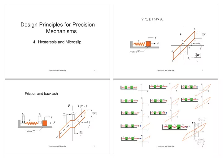
Design Principles for Precision 2 Mechanisms F 2 W f c 1 3 - - PowerPoint PPT Presentation

design principles for precision
SMART_READER_LITE
LIVE PREVIEW

Design Principles for Precision 2 Mechanisms F 2 W f c 1 3 - - PowerPoint PPT Presentation

Virtual Play s v Design Principles for Precision 2 Mechanisms F 2 W f c 1 3 4. Hysteresis and Microslip ( ) F arctan c L 0 f 4 Friction W 6 s v 2 W s v = c 5 Hysteresis and Microslip 1 Hysteresis and Microslip 2


slide-1
SLIDE 1

Design Principles for Precision Mechanisms

  • 4. Hysteresis and Microslip

1 Hysteresis and Microslip

F L f

Friction W

c

v

s W 2

( )

c arctan

F f c W sv 2 =

1 2 3 4 5 6

Virtual Play sv

2 Hysteresis and Microslip

Friction W

F L f c s1 s2

Friction and backlash

2 1

s s + W 2

( )

c arctan

F f

c W

if = W

c W

3 Hysteresis and Microslip 4 Hysteresis and Microslip

slide-2
SLIDE 2

F

f

1 3 7 2

Hysteresis curve with distributed friction and compliance

5 Hysteresis and Microslip

a b F N = : m equilibriu Moment a b c N cf F a b c N cf F µ µ µ µ 2 1 f F 2 2 1 f F 2 direction moving in m equilibriu + = − = − = + =

Friction is load dependent: the butterfly-tie

6 Hysteresis and Microslip

lower friction higher stiffness

Minimize virtual play

7 Hysteresis and Microslip

Hysteresis in clamped joints

  • uniform clamping pressure: σ

σ σ σv

  • friction coefficient: µ

µ µ µ

  • clamps are infinitely stiff
  • force transfer under slip

8 Hysteresis and Microslip

slide-3
SLIDE 3

Hysteresis in clamped joints

EA Fs ubeam = EA Fs uclamp 2 =

cross-section A

l EA cbeam = s EA cclamp 2 =

v v

b F s F b s σ µ σ µ ⋅ ⋅ ⋅ = → = ⋅ ⋅ ⋅ ⋅ 2 2

9 Hysteresis and Microslip

Alternating load in clamped joints

EA Fs sv 2 =

10 Hysteresis and Microslip

Minimising virtual play

t Eb F s bt A EA Fs s

v v v 2 2

4 ) ( 2 µ σ =

  • =

=

v

b F s σ µ ⋅ ⋅ ⋅ = 2

F

11 Hysteresis and Microslip

Hysteresis-free clamping

p c c p c c p p

E E A A E A E A = → ⋅ = ⋅

Clamping of a tapered beam is not very practical, maybe gluing is…

12 Hysteresis and Microslip

slide-4
SLIDE 4

Transfer of torques

analogies

tension glue seam tension glue seam

13 Hysteresis and Microslip

Hysteresis-loops, summary

14 Hysteresis and Microslip

Clamping a bush might cause axial displacement

15 Hysteresis and Microslip

Inaccurate z-positioning while clamping hubs (1/2)

16 Hysteresis and Microslip

slide-5
SLIDE 5

Inaccurate z-positioning while clamping hubs (2/2)

No axial slip if:

) and 3 . ( 4 ν µ ν ≈ = ⋅ > D L

17 Hysteresis and Microslip

Clamping optical system of radial follower CD system

18 Hysteresis and Microslip

Hysteresis in structures

19 Hysteresis and Microslip

Hysteresis in bolted connections (1/2)

preferebly high surface pressures

20 Hysteresis and Microslip

slide-6
SLIDE 6

Hysteresis in bolted connections (1/2)

21 Hysteresis and Microslip

A “bed of nails” for free-of-hysteresis clamping

22 Hysteresis and Microslip

Clamping a plate spring

2

2 y Ebt c finger =

Width: b

F

23 Hysteresis and Microslip

Stopping by means of clamping

24 Hysteresis and Microslip

slide-7
SLIDE 7

ϕ

  • l

v d vt 2 1 ⋅ =ϕ

  • v

w

F

l w

F ,

v

w

F d D

Rotation of the cork eleviates the friction

25 Hysteresis and Microslip

Alleviating friction by means of slip in a different direction

26 Hysteresis and Microslip

G h

l h G h l G µ µ 2 2 : if locking

  • self

< <

Self-locking

The locking can be alleviated when rotating the shaft:

α

µ α ⋅ = l h 2 sin

h Gl Fw ⋅ = µ 2 G Fw =

27 Hysteresis and Microslip

Self-aligning gear wheel

28 Hysteresis and Microslip

slide-8
SLIDE 8

Rapid and accurate tape feed mechanism

29 Hysteresis and Microslip

Self locking

α α α α

F F µ α < : if locking

  • self

α sin ⋅ F N W

30 Hysteresis and Microslip

virtual play self-locking ( )

c W W sv

2 1

2 + = ? N ?

1

W ?

2

W c

v

s µ µ α

Positioning against pins

31 Hysteresis and Microslip

The principle of self-positioning

32 Hysteresis and Microslip

slide-9
SLIDE 9

3 2 1 P1,2 n1 n2 n3

n

F

3 2 1 P1,2 n1 n2 n3

n

F ε ε ⋅ =

n

F M

(1) determine the poles and nesting torque direction Assumption: no friction in contacts!

33 Hysteresis and Microslip 3 2 1 P2,3 P1,3 P1,2

(1) determine the poles and nesting torque direction

34 Hysteresis and Microslip

(1) determine the poles and nesting torque direction

35 Hysteresis and Microslip 3 2 1 P1,2 n1 n2 n3

n

F

3 2 1 P1,2 n1 n2 n3

n

F

(2) determine the prohibited zones

36 Hysteresis and Microslip

slide-10
SLIDE 10

3 2 1 P2,3 P1,3 P1,2 n1 n2 n3

n

F

3 2 1 n1 n2 n3

n

F

R

F

1

R

2

R

3

R

(2) determine the prohibited zones

37 Hysteresis and Microslip 3 2 1

Fc Fc Fc

3 2 1

Fn

Alternative: find Fn on basis of equal pin reaction

38 Hysteresis and Microslip

Mn

(1) Or find Mn on basis of equal pin reaction

39 Hysteresis and Microslip

Now friction comes into play……

40 Hysteresis and Microslip

slide-11
SLIDE 11

1 , w

F

3 2 1 P1,2 n1 n2

n

F

3 2 1 P1,2 n1 n2

n

F

2 , w

F

r2 r1 ε

µ

41 Hysteresis and Microslip 3 2 1 P2,3 P1,3 P1,2 n1 n2 n3

n

F

3 2 1 P2,3 P1,3 P1,2

n

F

42 Hysteresis and Microslip

R M 3 l l D y

43 Hysteresis and Microslip f ϕ P x

F

A B l L − l L C L

∆ R M l L − L

Shortening ideal rotation

44 Hysteresis and Microslip

slide-12
SLIDE 12

n

F

A B

M O Well-defined line of action of the nesting force Fn

45 Hysteresis and Microslip