Design and Implementation of the Bio-Networking Architecture Jun - - PDF document

design and implementation of the bio networking
SMART_READER_LITE
LIVE PREVIEW

Design and Implementation of the Bio-Networking Architecture Jun - - PDF document

Design and Implementation of the Bio-Networking Architecture Jun Suzuki, Tadashi Nakano and Tatsuya Suda {jsuzuki, tnakano, suda}@ics.uci.edu http://netresearch.ics.uci.edu/bionet/ Dept. of Information and Computer Science University of


slide-1
SLIDE 1

1

1

Design and Implementation of the Bio-Networking Architecture

Jun Suzuki, Tadashi Nakano and Tatsuya Suda

{jsuzuki, tnakano, suda}@ics.uci.edu http://netresearch.ics.uci.edu/bionet/

  • Dept. of Information and Computer Science

University of California, Irvine

2

Overview

  • Introduction to the Bio-Networking Architecture

– Motivations – Biological concepts applied – General design of the Bio-Networking Architecture

  • Simulation Study of

– Static adaptation scenarios – Dynamic adaptation scenarios

  • Empirical implementation of the Bio-Networking

Architecture

– Design, implementation and measurements of the Bio- Networking platform – On-going work

slide-2
SLIDE 2

2

3

Introduction to the Bio-Networking Architecture

4

Motivation

  • Computer network environment is becoming larger and

more complex.

  • Need a self-organizing network that supports

– scalability in terms of # of objects and network nodes, – adaptability to changes in network conditions, – availability/survivability from massive failures and attacks, – simplicity to design and maintain.

  • Our solution: apply biological concepts and mechanisms

to network application design

– Biological systems have overcome the above features.

  • e.g. bee colony, bird flock, fish school, etc.
  • The Bio-Networking Architecture is a new framework

– for developing large-scale, highly distributed, heterogeneous, and dynamic network applications.

slide-3
SLIDE 3

3

5

Biological Concepts Applied

  • Decentralized system organization

– Biological systems

  • consist of autonomous entities (e.g. bees in a bee colony)
  • no centralized (leader) entity (e.g. a leader in a bird flock)

– Decentralization increases scalability and survivability of biological systems.

– The Bio-Networking Architecture

  • biological entities = cyber-entities (CEs)

– the smallest component in an application – provides a functional service related to the application – autonomous with simple behaviors » replication, reproduction, migration, death, etc. » makes its own behavioral decision according to its own policy

  • no centralized entity among CEs

6

  • Emergence

– Biological systems

  • Useful group behavior (e.g. adaptability and survivability)

emerges from autonomous local interaction of individuals with simple behaviors.

– i.e. not by direction of a centralized (leader) entity – e.g. food gathering function » When a bee colony needs more food, a number of bees will go to the flower patches to gather nectar. » When food storage is near its capacity, only a few bees will leave the hive.

– The Bio-Networking Architecture

  • CEs autonomously

– sense local/nearby environment » e.g. existence of neighboring CEs, existence/movement of users, workload, availability of resources (e.g. memory space), etc. – invoke behaviors according to the condition in a local/nearby environment – interacts with each other

slide-4
SLIDE 4

4

7

  • Lifecycle

– Biological systems

  • Each entity strives to seek and consume food for living.
  • Some entities replicate and/or reproduce children with partners.

– The Bio-Networking Architecture

  • Each CE stores and expends energy for living.

– gains energy in exchange for providing its service to other CEs – expends energy for performing its behaviors, utilizing resources (e.g. CPU and memory), and invoking another CE’s service.

  • Each CE replicates itself and reproduce a child with a partner.

8

  • Evolution

– Biological system

  • adjusts itself for environmental changes through species

diversity and natural selection

– The Bio-Networking Architecture

  • CEs evolve by

– generating behavioral diversity among them, and » CEs with a variety of behavioral policies are created by human developers manually, or through mutation (during replication and reproduction) and crossover (during reproduction) – executing natural selection. » death from energy starvation » tendency to replicate/reproduce from energy abundance

slide-5
SLIDE 5

5

9

  • Social networking

– Biological systems (social systems)

  • Any two entities can be linked in a short path through relationships among

entities.

– not through any centralized entity (e.g. directory), rather in a decentralized manner. – six decrees of separation

– The Bio-Networking Architecture

  • CEs are linked with each other using relationships.

– A relationship contains some properties about other CEs (e.g. unique ID, name, reference, service type, etc.)

  • Relationships are used for a CE to search other CEs.

– Search queries originate from a CE, and travel from CE to CE through relationships.

  • The strength of relationship is used for prioritizing different relationships in

discovery.

– A CE may change its relationship strength based on the degree of similarity between two CEs. – The stronger relationship is likely to lead a query to a successful discovery result.

10

Design Strategy of the Bio-Networking Architecture

  • Separate cyber-entity (CE) and Bio-Networking

Platform (bionet platform),

– Cyber-entity (CE)

  • mobile object (agent) that provides any service

– Bionet platform

  • middleware system for deploying and executing CEs
  • Implement CE and bionet platform in Java
slide-6
SLIDE 6

6

11

Devise Bionet platform

Cyber-entities running

  • n a bionet platform

Attributes Body Behaviors cyber-entity users

CE’s Structure and Behaviors

  • Behaviors

– Energy exchange and storage – Communication – Migration – Replication and reproduction – Death – Relationship establishment – Social networking (discovery) – Resource sensing – State change

  • Attributes

– ID – Relationship list – Age – …etc.

  • Body

– Executable code – Non-executable data

12

Research Strategy

  • Simulation work to investigate if applied biological

concepts work well

– Adaptation through evolutionary process – Social networking (decentralized discovery)

  • Empirical implementation work to deploy the Bio-

Networking Architecture on actual networks.

– Implementation of the Bio-Networking Platform (bionet platform)

slide-7
SLIDE 7

7

13

Simulation Study: Adaptation and Evolution

14

Introduction

  • Goal:

– To optimize the behaviors of cyber-entities (replication and migration) in order to make a network application more efficient

  • Approach:

– Applying evolutionary mechanisms in the cyber- entity

slide-8
SLIDE 8

8

15

Reproduction and Migration Policies

Policy Parameter Set

Factor weight 1 Factor weight 2 threshold Migration Policy Parameters Factor weight 1 Factor weight 2 Factor weight 3 threshold Reproduction Policy Parameters Request Rate Factor Encourage a CE to migrate toward a requesting user Resource Cost Factor Encourage a CE to migrate toward a cheaper resource cost node Population Density Factor Encourage a CE to migrate away from a node when the number of CEs is increasing Wander Factor Encourage a CE to randomly chose a node to migrate to.

Migration Policy Factors used in this simulation

∑ =

> ⋅

n i i i

Migrate then M F W If ,

Gene model for a cyber-entity Migration Policy:

16

Evolutionary Mechanisms

  • Evolutionary mechanisms are incorporated in

replication and reproduction, generating diverse cyber-entity entities.

  • Natural selection (energy) keeps fitter cyber-

entities while eliminating inefficient cyber-entities.

  • The repeated interaction between generating

diversity and natural selection enables evolution.

slide-9
SLIDE 9

9

17

Evolutionary Mechanisms

  • In replication, mutation occurs.

– Change a weight of a factor

Policy Parameter Set

Factor weight 1 Factor weight 2 threshold Migration Policy Parameters Factor weight 1 Factor weight 2 Factor weight 3 threshold Reproduction Policy Parameters

Policy Parameter Set

Factor weight 1 Factor weight 2 threshold Migration Policy Parameters Factor weight 1 Factor weight 2’ Factor weight 3 threshold Reproduction Policy Parameters 18

Evolutionary Mechanisms

  • Reproduction involves two steps.

– Local partner selection and crossover (possibly with mutation)

  • Local Partner Selection

– Reproducing entity selects a partner on the platform or nearby platforms, – based on three selection criteria: waiting time, hop count, and energy efficiency

slide-10
SLIDE 10

10

19

  • Waiting time: the average time of a service request being

stored at a platform before the cyber-entity processes the service request

  • Hop count: the average distance between a requesting user

and the cyber-entity that processes the request

  • Energy efficiency: The consumed energy / [acquired

energy + consumed energy].

  • A partner entity is probabilistically selected according to

– these performance of the reproducing entity and, – predefined performance requirements. – e.g., when the partner selecting cyber-entity is inefficient to satisfy a pre-defined level of energy gain, maximizing energy efficiency may be chosen as the

  • bjective goal to improve.

20

Policy Parameter Set Factor weight 1 Factor weight 2 threshold Migration Policy Parameters Factor weight 1 Factor weight 2 Factor weight 3 threshold Reproduction Policy Parameters Policy Parameter Set Factor weight 1 Factor weight 2 threshold Migration Policy Parameters Factor weight 1 Factor weight 2 Factor weight 3 threshold Reproduction Policy Parameters Policy Parameter Set Factor weight 1 Factor weight 2 threshold Migration Policy Parameters Factor weight 1 Factor weight 2 Factor weight 3 threshold Reproduction Policy Parameters

Parents cyber-entities reproduced cyber-entity

Crossover

  • Crossover

– Behavior policies of parents cyber-entity are mixed and transferred to the next generation (reproduced cyber-entity).

  • Mutation

– Can occur in a same way as in replication.

Evolutionary Mechanisms

slide-11
SLIDE 11

11

21

Platforms

  • Network topology: 8x8
  • Charge 5 energy units to an

entity for computing resources

  • Charge 100 energy units for

each behavior

  • TTL set to 5 hop counts

Simulated network and the user request rate / sec

User Request

  • Constant request rate (number

in the circle)

  • Pay 10 energy units for a

service (CE)

  • Forwarded to the nearest CE

(node)

  • A maximum of 500 request

messages stored in a node queue

5 10 20 5 5 5 5 30 15 5 5 5 5 15 10 15 5 10 15 5 5 5 5 10 15

2.0

  • M. Threshold

0.5 M.Wandering 1.0

  • M. Population Density

Ratio 0.5

  • M. Resource Cost Ratio

1.0

  • M. Request Rate Ratio

0.5

  • R. Threshold

0.1

  • R. Request Rate

PR

Cyber Entities

  • 10000 energy unit given
  • Placed on the center
  • Request processing time: 0.2

sec

  • Die at the age of 1 simulated

hour

  • 3000 energy units are given by

the reproducing parent to its child

Simulation Configurations

22

Evaluation Criteria

  • Response Time:

– Waiting time of a service request at a platform and network delay of the request

  • Hop Count:

– The average distance between a requesting user and the cyber-entity that processes the request

  • Energy Gain:

– The difference between acquired energy and consumed energy.

slide-12
SLIDE 12

12

23

Performance of PR - Energy Gain and Response Time -

Energy gain is improved:

as time progresses, the cyber-entity's behavior is

  • ptimized through evolution.

Evolution creates a cyber-

entity that can actively migrate around networks, which finally finds new energy sources (user request).

Response time is also

improved: Successfully adjusted the number of cyber- entity as a result of

  • ptimization in reproduction

behavior.

24

Performance of PR – Hop Count an a population number -

Hop Count is improved:

migration behavior is

  • ptimized. Cyber-entities

weaken migration behavior

  • nce users are found (,since

all the users never move.)

Some simulated time later,

the total population number becomes stable, and seems to converge to a certain number.

slide-13
SLIDE 13

13

25

Simulation Summary

  • Cyber-entities successfully evolve and adapt to simulation

environments.

  • (not shown today’s talk, but) various types of cyber-entities

and network environments are examined,

– Randomly walking users – Different resource cost environment – Unstable network with topological changes

26

Bio-Networking Platform

slide-14
SLIDE 14

14

27

The Bio-Networking Platform

  • The Bio-Networking platform (bionet platform)

– is a middleware system that provides reusable software components for deploying and executing cyber-entities.

  • abstract low-level operating and networking details (e.g. I/O,

concurrency, messaging and network connection management) and,

  • provide a set of runtime services that CEs frequently use for

– performing their services, – sensing network environment, and – invoking their biological behaviors.

28

Architecture of the Bio-Networking Platform

Bionet Services Bionet Platform

Bionet Container

CE

CE Context

CE

Java VM

Bionet Message Transport

A Cyber-entity (CE) is an autonomous mobile object. CEs communicate with each

  • ther using FIPA ACL.

A CE context provides references to available bionet services. Bionet services are runtime services that CEs use frequently. Bionet container dispatches incoming messages to target CEs. Bionet class loader loads byte code of CEs to Java VM. Bionet message transport takes care of I/O, low-level messaging and concurrency.

Bionet Class Loader

slide-15
SLIDE 15

15

29

Bionet Message Transport

  • Bionet message transport abstracts low-level
  • perating and networking details such as I/O,

concurrency, messaging, network connection management.

– Marshaling/unmarshaling of messages issued by a CE

  • GIOP/IIOP used currently

– TCP connection setup and management – Message delivery on a TCP connection

  • One-to-one messaging, currently
  • One-to-many broadcasting/multicasting (future work)

– Threading (thread pooling) to accept incoming messages

30

Bionet Container

  • Bionet container dispatches incoming messages to

target CEs.

– Demultiplexing incoming messages – Dispatching incoming messages to target CEs – Creating CE references – Activating and de-activating CEs

slide-16
SLIDE 16

16

31

Bionet Services

  • CEs use bionet services to invoke their behaviors.

– e.g. bionet lifecycle service when a CE replicates

  • Each bionet platform provides 9 bionet services

– Bionet Lifecycle Service

  • allows a CE to change its state.
  • maintains a thread pool that contains threads assigned to autonomous CEs
  • allows a CE to replicate itself and reproduces a child CE with a partner.
  • allows a CE to reproduce a child CE with a partner
  • Mutation and crossover during replication and reproduction

– Bionet Relationship Management Service

  • allows a CE to establish, examine, update and eliminate their relationships

with other CEs.

32

– Bionet Energy Management Service

  • keeps track of energy level of the CEs running on a local

platform.

  • allows a CE to pay energy for

– invoking a service provided by another CE, – using resources, and – performing behaviors (i.e. invoking a bionet service).

– Bionet Resource Sensing Service

  • allows CEs to sense the type, amount and unit cost of available

resources (CPU and memory).

– CPU availability = Nidle_threads/Nmax_threads » where Nidle_threads is the number of idle threads in a thread pool maintained by bionet lifecycle service, and » Nmax_threads is the max number of threads in the thread pool. – Memory availability = Mfree/Mmax » where Mfree is the amount of memory available on Java VM, and » Mmax is the max size of memory allocated to Java VM. – Resource unit cost is determined based on resource availability.

slide-17
SLIDE 17

17

33

– Bionet CE Sensing Service

  • allows a CE to discover other CEs running on neighboring

bionet platforms reachable in N hops (platform-level discovery).

– N = 0; discovery of local CEs running on the same platform. – N > 0; discovery of remote CEs running on different platforms.

– Bionet Pheromone Emission/Sensing Service

  • allows a CE to leave its pheromone (trace) on a local platform

when it migrates to another platform

– so that other CEs can find the CE at a destination platform

  • allows a CE to let other CEs know of its existence by

broadcasting its metadata.

– Other CEs may come to interact with the CE or establish a relationship with the CE.

34

– Bionet Topology Sensing Service

  • allows a CE to sense the connectivity among neighboring

bionet platforms reachable N hops.

– proactive sensing – reactive sensing – hybrid sensing – static sensing

– Bionet Social Networking Service

  • allows a CE to search other CEs through their relationships

(CE-level discovery).

– Bionet Migration Service

  • allows a CE to migrate to another bionet platform.
slide-18
SLIDE 18

18

35

Cyber-entity

  • CEs communicate with each other through:

– interface CyberEntity {

  • neway void send(in string message);

string metadata(); }; – A subset of FIPA ACL with some extensions is used as a communication language.

  • encoded with XML
  • Implemented as Java mobile code

Cy Cybe ber-entity send() metadata() Message queue Environment sensing Behavior selection messages messages Behavior invocation Cy Cybe ber-entity send() metadata() Message queue Environment sensing Behavior selection messages messages Behavior invocation

  • Each CE uses an individual

thread to continuously

– sense the nearby environment, – identify behaviors suitable for the current environment condition, and – invoke the most suitable behavior

36

  • An autonomous CE

– receives messages from other cyber-entities. – continuously senses nearby environment and performs its behaviors. – runs on an individual thread; thus, expends energy continuously for using a thread (CPU) and memory space.

  • An active CE

– is ready for receiving messages from other cyber-entities, but – does not perform behaviors – consumes memory; thus expends energy continuously for using memory space.

  • An inactive CE

– is in “sleeping” state in which it is externalized into a file – does not expend energy because it does not consume any resources.

autonomous active inactive Not exists (dead) autonomous active inactive Not exists (dead)

Each CE may have 4 states during its lifetime. It changes its state voluntarily; any CEs are not allowed to change another CE’s state.

slide-19
SLIDE 19

19

37

Implementation Status

  • Every component in the bionet platform has been

implemented,

– except the bionet topology sensing service. – Bionet message transport and bionet container are implemented based on the CORBA specification.

  • Our own CORBA implementation, called muORB
  • Publicly available CORBA implementation called JacORB
  • Measurements and documentation underway

– netresearch.ics.uci.edu/bionet/resources/platform/

38

Standardization Effort at OMG

  • A goal of the OMG Super Distributed Objects (SDOs)

working group is to

– provide a standard computing infrastructure for highly distributed ubiquitous networking systems.

  • SDO is a logical representation of a hardware device (e.g.,

PDA, AV device and refrigerator) and software component.

  • Status:

– The SDO RFI issued (‘00), and responses gathered (‘01)

  • from 10 organizations including UCI

– The SDO white paper published (‘01) – The first RFP published (‘02).

  • the resource data model for SDOs and the interfaces that SDOs implement.

– Hitachi, GMD Fokus and UCI will submit the joint revised specification in March ’03.

  • Several key constructs in the Bio-Networking Architecture have been

reflected (e.g. CE’s attributes such as energy level, relationship, relationship attributes such as relationship strength)

slide-20
SLIDE 20

20

39

Preliminary Measurement Results

40

Message Transmission Latency

A sender CE dynamically selects a receiver CE at random, and sends an empty string message to the selected CE.

Measurements were conducted within a single machine with Java 1.4 VM, Win XP, and 1GHz Pentium 3 CPU. 64 MB heap allocated to each Java VM

  • What we measured

– Latency for message transmission between two CEs

  • How long it takes for a CE to send a message to another CE?
  • Overhead sources to message transmission

– Marshaling a message issued by a sender CE, – TCP connection setup, – message delivery on the connection, – message dispatching to a receiver CE, and – unmarshaling of an incoming message.

CE Java VM Bionet Message Transport OS Bionet Container CE Java VM Bionet Message Transport CE CE CE CE

sender CE receiver CEs

slide-21
SLIDE 21

21

41

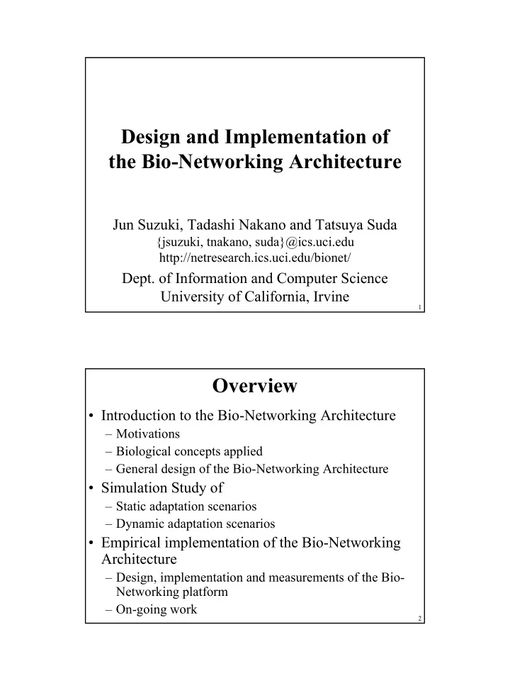
0.05 0.1 0.15 0.2 0.25 0.3 0.35 1 100 200 300 400 500 600 700 800 900 1000 # of receiver cyber-entities (objects) Latency (msec) Bionet JacORB Java IDL ZEN

A single sender CE and a range of receiver CEs (1, 100, …1000) were deployed.

Bionet platform was compared with existing distributed object platforms implemented in Java.

  • Measurement results and observations

– Bionet message transport and container are fairly efficient and comparable with existing distributed object platforms.

  • Message transmission latency was 0.17 msec when 1,000 receiver CEs were

deployed.

– Bionet message transport and container are scalable in terms of the number of receiver CEs.

  • Latency is relatively constant when the number of CEs grows, rather than it increases

linearly (the average of latency was 0.179 msec.). – In general, increasing the # of receiver CEs increases the effort to establish TCP connections to receiver CEs (in sender side) and demultiplex/dispatch incoming messages to target CEs (in receiver side).

  • Implementation techniques such as connection sharing and hash-based

demultiplexing work well.

42

A sender CE selects a receiver CE at random before a measurement, and sends empty string messages to the selected CE.

Measurements were conducted within a single machine with Java 1.4 VM, Win XP, and 1GHz Pentium 3 CPU. 64 MB heap allocated to each Java VM

  • What we measured

– throughput of a CE

  • How many messages a CE can receive and process in a second?
  • The throughput is dominantly affected by

– message demultiplexing in bionet container.

CE Java VM Bionet Message Transport OS Bionet Container CE Java VM Bionet Message Transport CE CE CE CE

sender CE receiver CEs

Message Throughput

slide-22
SLIDE 22

22

43

A single sender CE and a range

  • f receiver CEs (1, 100,

…1000) were deployed. Bionet platform was compared with existing distributed object platforms implemented in Java.

500 1000 1500 2000 2500 3000 3500 1 100 200 300 400 500 600 700 800 900 1000 # of cyber-entities (objects) Throughput (calls/sec) Bionet JacORB Java IDL ZEN

  • Measurement results and observations

– The throughput of a CE on a bionet platform is competitive with existing distributed object platforms.

  • Throughput was 2279.99 messages/sec when 1,000 receiver CEs were deployed.

– Bionet container are scalable in terms of the number of receiver CEs.

  • Increasing the number of receiver CEs increases the demultiplexing effort.

Throughput remains relatively constant as the number of receiver CEs grows (2309.27 messages/sec in average), rather than it increases linearly.

  • Implementation technique of hash-based demultiplexing works well.

44

On-going Work

slide-23
SLIDE 23

23

45

Empirical adaptability of CEs

  • Empirical implementation of evolutionary

adaptation mechanism

– Has implemented a framework to define and manipulate behavioral policies (factor, weight and threshold values). – Now implementing CE’s behavior selection mechanism

  • to calculate weighted sum of factor values, compare it with a

threshold value, and invoke a corresponding behavior.

– Will evaluate empirical adaptability of CEs on actual network environments soon.

46

Reconfigurability of Bionet Platform

  • Motivations to reconfigure bionet platform

– Every user and application does not require every functionalities/services provided by the bionet platform. – Every network node probably cannot deploy all the components in the bionet platform due to resource constraint.

  • Approach to reconfigure middleware

– Compose middleware as a set of components. – Middleware

  • sense its context such as available resources and systems current

configuration.

  • determine a strategy to reconfigure middleware according to the obtained

context.

  • execute the determined reconfiguration strategy.
  • Our goal is to investigate the adaptability of networking

system by making not only network applications but also underlying middleware systems to be reconfigurable.

slide-24
SLIDE 24

24

47

  • Design (re-design) bionet

services and major functionalities in a bionet service as middleware components

  • Insert a reconfiguration

layer into the bionet platform

  • The reconfiguration layer

manages and controls middleware components.

– Dependency mgt. – Consistency mgt. – Query/lookup for middleware components – Loading/unloading middleware components – Environment sensing

Bionet Services Bionet Platform

Bionet Container

CE

CE Context

CE

Java VM

Bionet Message Transport

Bionet Class Loader

Reconfiguration Layer

48

Thank you

  • All the papers/documents are available at:

– Project web site:

  • netresearch.ics.uci.edu/bionet/

– Bionet simulator

  • netresearch.ics.uci.edu/bionet/resources/evolution_simulator/

– Bionet platform

  • netresearch.ics.uci.edu/bionet/resources/platform/
  • Sponsors

– NSF (National Science Foundation) – DARPA (Defense Advanced Research Program Agency) – AFOSR (Air Force Office of Science Research) – State of California (MICRO program) – Hitachi – Hitachi America – Novell – NTT (Nippon Telegraph and Telephone Corporation) – NTT Docomo – Fujitsu – NS Solutions Corporation