
SLIDE 1
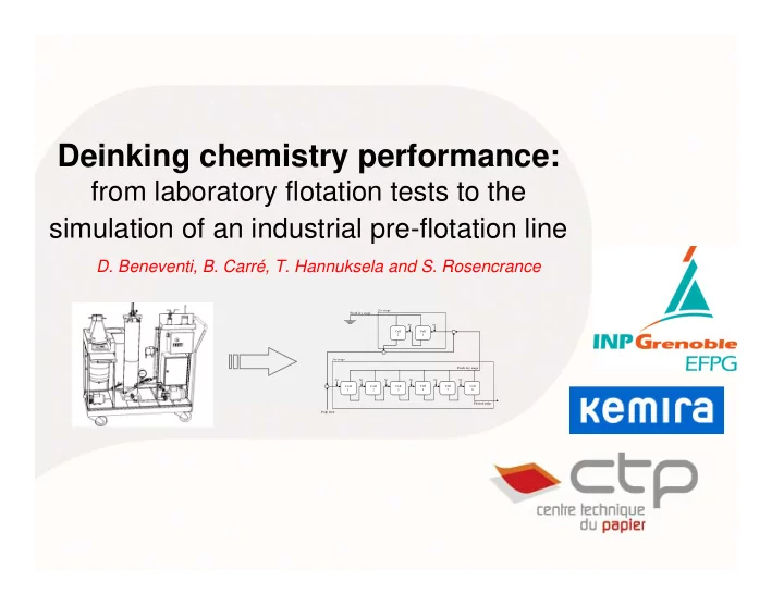
Deinking chemistry performance:
from laboratory flotation tests to the simulation of an industrial pre-flotation line
- D. Beneventi, B. Carré, T. Hannuksela and S. Rosencrance