Chemistry Input to Flow Assurance Colin Smith Production Chemistry - - PowerPoint PPT Presentation

chemistry input to flow assurance
SMART_READER_LITE
LIVE PREVIEW

Chemistry Input to Flow Assurance Colin Smith Production Chemistry - - PowerPoint PPT Presentation

Production Chemistry Networking Event 3 A Holistic Systems Approach to Production Chemistry Input to Flow Assurance Colin Smith Production Chemistry Technical Authority E-mail: Colin.Smith@woodplc.com Tel: +44 (0)1784 417154 Event date:


slide-1
SLIDE 1

woodplc.com

Production Chemistry Networking Event 3 A Holistic Systems Approach to Production Chemistry Input to Flow Assurance

Colin Smith – Production Chemistry Technical Authority E-mail: Colin.Smith@woodplc.com Tel: +44 (0)1784 417154 Event date: 02/10/2018 Event hosted by Richard Barr, Proserv

slide-2
SLIDE 2

What is Production Chemistry?

2 A presentation by Wood. October 2018

Impact Gas Water Liquid Hydrocarbons Production

Hydrates Emulsions, Scale, Sand/fines Wax, Asphaltenes, Naphthenates, Foaming

Product Value

H2S, CO2, DMS, Mercaptans, Mercury Desalination, SRP, PWRI, Reuse, Unconventional BS&W, Sulphur, Mercury, Organic chloride

Asset Integrity

H2S, CO2, chemicals, Corrosion Chloride, Bacteria, Sand, Hg, Corrosion Organic acids, Organochlorides

Environmental / HSE Compliance

Flaring / Emissions Oil in water, WSOs, Contaminants, NORM/LSA Scale Oil in water Organic Mercury

Prod

  • duction

ction Chemistry istry is the management of the chemical properties of fluids that can impact production, product value, asset integrity or environmental/HSE compliance

slide-3
SLIDE 3

Unmitigated Production Chemistry - 1

3 A presentation by Wood. October 2018

GAS HYDRATES NORM SCALE WAX- PIGGING DEBRIS ASPHALTENE FLOCCULATION

B L O C K A G E S

slide-4
SLIDE 4

Unmitigated Production Chemistry - 2

4 A presentation by Wood. October 2018

CALCIUM NAPHTHENATE (CaN) CORROSION

slide-5
SLIDE 5

Production Chemistry Issue - Severity

5 A presentation by Wood.

PC / FA Issue Location of Fouling / Deposition Fouling / Deposition to Form Blockage - Severity Production Flow Period to See a Problem Hydrates Subsea Very High Hours - Days Halite Downhole/subsea Very High Days Naphthenates Topsides High 2 – 4 weeks Asphaltenes Downhole Medium to High Months Wax Downhole/Subsea Medium to High 4 weeks to 3 months Scale Downhole / Subsea / T

  • psides

Medium to High > 6 months typically (can be < 3 months) Biofilms / Biofouling Subsea Medium to Low > 6 months to years Emulsions All Low Years Sand (assumed well

completions hinder sand production rate)

Topsides Low Years Consider dering ng worst st case e scenario nario – uncontr

  • ntroll

lled ed product uctio ion, n, ~ 120 Kbopd

slide-6
SLIDE 6

New Oil & Gas Field Development Projects

6 A presentation by Wood. October 2018

Typically between Appraise-Concept Select-Define phases Project Team

  • Project Lead/Manager/Engineer
  • Front End Engineer(s)
  • Process Engineer(s)
  • Reservoir Engineer(s)
  • Subsea Engineering Specialists
  • Corrosion / Materials Engineer
  • Production Technology / Petroleum Engineering (Wells)
  • Flow Assurance Engineer(s)
  • Process Chemist

A collaborative team approach!

  • No working in isolation
  • Constant communication, data sharing / review
  • Regular team meetings / workshops / peer reviews
  • Joint reports
slide-7
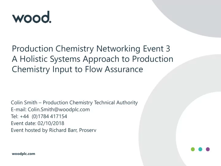
SLIDE 7

Project Life Cycle – FA/PC/Process Activities

7 A presentation by Wood. October 2018

Exploration & Appraisal Concept Select Define Execute Operate

Life of Field Operation Decommission

Core Analysi ysis & Geochemistry Longe ger Term Water Injection

  • Studies. EOR,

Chemical Squeeze Onsite & Lab Core Flooding Formation & Injection Water Composition

CO2, H2S, He, RSH, Hg, Radon, Arsenic, Vanadium, Calcium Naphthenate

Contaminants

PC Risks ks: Scaling, Asphaltene, Wax deposition, CaN

PVT Analysis Implications Well Test Sampling SoW Chemical Injection Design, Chemical HSE BOD Start-up, Shut- down Strategies FEED, Flowline Design, Field Layout Mitigation Philosophies & Strategies Fluid & Material Compatibilities Hydrate, Wax, Corrosion, Asphaltene, Scale Deposition Modelling Corrosion and Chemical Monitoring Chemical Management Onsite Lab Design Operating and Lab Procedures Commissioning Plan Wet Lay-up, Hydrotesting Chemical Packages Chemical Selection & Qualification Commissioning Support System Performance Monitoring & Evaluation EOR Options Well Workover Process & Chemical Optimisation FDP, WFSs, BfD, CSR, prelim CRR Final CRR Oil assays, oils blending tests

slide-8
SLIDE 8
  • Hydrocarbon phases properties & composition

– Oil, gas, condensate, reservoir fluid

  • Formation water properties & composition (contamination)
  • Gas phase issues

– Corrosion – Hydrates – Souring / H2S

  • Oil / Condensate phase issues

– Asphaltenes – Wax (deposition and gelation) – Corrosion – Emulsions / rheology / separation / foaming – Naphthenates & Soaps – Scaling (incl. NORM, halite, sulphides etc.)

  • Prod. Chem. Input to Flow Assurance – 1

8 A presentation by Wood. October 2018

slide-9
SLIDE 9
  • Water phase

– Scaling – Corrosion – Separation / Emulsions – Microbiology – Produced water treatment – Water Injection / recycle / reuse / disposal

  • Contaminants – Across all phases

– Organic acids – Sulphur species – Heavy metals, e.g. Mercury – Arsenic / arsenates – Organochlorides

  • Use of Analogue fields fluid data if have no samples/poor samples
  • Understand your fluids – define the issues – A correct basis is a

must!

  • Prod. Chem. Input to Flow Assurance – 2

9 A presentation by Wood. October 2018

slide-10
SLIDE 10

PC & FA Workflows

10 A presentation by Wood.

FA & PC new oil & gas field developments workflows

  • Oversee production fluid characterisation studies
  • Collaboration = well defined fluids basis of design (BoD)
  • Risk assess for wax, asphaltenes, hydrates, emulsions, foaming,

souring, corrosion, scaling, soaps, contaminants, water treatment etc.

  • Combination of modelling, lab experiment & analysis work
  • Define PC/FA problem solutions – design, operational &

chemical solutions

  • Oversee the screening & qualification of chemicals &

compatibility

  • Compile Chemical Requirements Reports (CRRs)
  • Develop mitigation strategies
  • incl. Chemical Management Strategy (CMS)
slide-11
SLIDE 11

Asphaltene Risk Assessment Workflows

11 A presentation by Wood. October 2018

slide-12
SLIDE 12

PC – FA Work Program - 1

12 A presentation by Wood. October 2018

  • Develop and set the Production Fluids Basis
  • Formation Water composition / properties
  • Hydrocarbon oil/condensate properties
  • Gas composition
  • Contaminants
  • Identify any BoD gaps/uncertainties requiring further work (Holds)
  • Perform lab testing required to fill any basis data gaps
  • Actual or restored samples requirement
  • Identify best labs to do fluid properties work, e.g. oil/condensate

liquid properties

  • agree SoW, generate RFQs, send to labs & review responses
  • select best laboratory for work & generate PO
  • versee lab testing & handle any queries,
  • Review laboratory testing report
  • interpret results for project
  • Run simulation modelling as required, e.g. scaling predictions
slide-13
SLIDE 13

PC – FA Work Program - 2

13 A presentation by Wood. October 2018

  • Full Production Chemistry risks assessment developed

(including modelling & comparison to analogues, as required)

  • Hydrates
  • Scale (including halite for FW breakthrough case)
  • Corrosion
  • Emulsions / separation (soaps)
  • Foaming
  • Wax,
  • Asphaltenes
  • Naphthenates
  • Contaminants (including Mercury) & meeting export specs
  • Produced water treatment aspects
  • Microbiology (biofouling risk)
  • Full FA risks assessment performed – PC/FA data exchanged
  • Rank the PC/FA risks & flag up those needing chemical control
slide-14
SLIDE 14

PC – FA Work Program - 3

14 A presentation by Wood. October 2018

  • Define high level chemical requirements to control any identified

risks

  • Hydrates
  • Corrosion
  • Scale (+ halite?)
  • Emulsions / separation & produced water treatment (PWT)
  • Liaise with project disciplines – define system conditions under

which chemicals will be applied (e.g. P, T, flow regime, shear stress etc.) including if any need for downhole injection – Liaise with FA

  • Engage various chemical vendors for their recommended chemical
  • ptions & their product application ranges / limitations
  • Product stability,
  • Product performance,
  • Environmental aspects
  • Product compatibility characteristics
  • Input into umbilical core chemical requirements
slide-15
SLIDE 15

PC – FA Work Program - 4

15 A presentation by Wood. October 2018

  • Oversee any laboratory qualification testing of recommended

chemicals, define target chemical injection rates, select injection locations & interpret test results for project

  • Define SoW, RFQs to labs, select a lab, interpret results
  • Investigate compatibility of tieback and hub production fluids
  • Investigate compatibility of treatment chemicals
  • With production fluids
  • With selected materials (steels, elastomers)
  • With hub production fluids
  • With hub treatment chemicals
  • Any common chemicals possible?
  • Work with other disciplines (e.g. FA, subsea) to design the chemical

injection facilities (downhole, subsea & topsides, plus umbilical)

  • Define

number

  • f

cores needed, core diameters, chemical deliverability etc.

slide-16
SLIDE 16

PC – FA Work Program - 5

16 A presentation by Wood. October 2018

  • Field production chemicals regulatory requirements preparation

before EXECUTE phase

  • HSSE,
  • Environmental,
  • Chemical permitting etc.
  • FA Summary report generated
  • Ongoing throughout – generate a Chemical Requirements Report,

CRR

  • A catch all ‘live’ document
  • Move into FEED or done during FEED / pre-FEED
slide-17
SLIDE 17

Production Chemistry & FA Integration

October 2018

  • Representative

fluid samples required

  • Sample

testing provides experimental data (wax, asphaltenes, hydrates etc.)

  • FA

modelling provides risk assessments for different scenarios & helps decision making on the

  • verall concept
  • Comparison of lab test data & FA

models output – tune and validate the models

  • Apply operational experience
  • Use analogues knowledge
  • Apply lessons learned
  • Co-operation

is key to yielding representative results

PC+FA A Involve lvement ment PC+FA A Involve lvement ment

slide-18
SLIDE 18

When it goes right! (subsea tieback to existing hub)

  • Steady state flow covered – mitigations agreed by team
  • Transient operations covered (start-up/restart/shutdowns)

– E.g. hydrate management (THIs, KHIs, cocktails)

  • Impact of flow regime/slugging/surges/Liquid hold up) – line/riser
  • Chemical injection locations agreed by project team
  • Chemical injection facilities designed with flexibility (+sparing) for life of

field (plus storage requirements, cleanliness etc.) – Allow for low to high production rates (+ turndown) – Allow for compositional changes (e.g. inj. water breakthrough)

  • CIMVs option considered collectively (team)
  • Umbilical core design & chemicals deliverability optimal/flexible
  • Chemical compatibility / core flushing / environmental impacts
  • Operating philosophies and management strategies developed

collectively by various disciplines

Proactive PC – FA Collaboration - Output

October 2018

slide-19
SLIDE 19

Wax related properties derived in laboratory (dead / live fluids)

– Used for tuning FA modelling of wax deposition in subsea pipelines – For different scenarios look at live WAT vs arrival temperatures – Impact of pressure/gas/water on gel strength / restart pressure – Drive wax management strategies – Select insulation/heating/pigging/chemicals etc.

PC – FA Key Collaboration – Wax Example

October 2018

Exploration Identify & Assess WAT / WDT Wax Content Pour Point (PP) Viscosity Appraisal / Development Identify & Assess / Select Further WAT / PP tests HTGC Yield Stress / Restart Wax Deposition Rate Live WAT determination Development Select Chemical Tests Thermodynamic Modelling Deposition Modelling Flow Loops R&D

Required Optional

slide-20
SLIDE 20

Laboratory Testing - Wax

20 A presentation by Wood.

Gelation tion / Pipeline line Resta tart

Pour Point Yield Stress / Pressure

Deposi sition tion

WAT Viscosity HTGC Analysis Wax Diffusion Coefficient

slide-21
SLIDE 21

Hydrate Risk Assessment – Lab Experiments

21 A presentation by Wood. October 2018

Temperature: -80 to +250 oC Pressure: 6,000 psia (400 bar) 10,000 psia (700 bar) 30,000 psia (2,000 bar)

Visual Autoclave Rocking Autoclave High Pressure Cell

Run lab experiments under different conditions and plot experimental points on model hydrate curves

slide-22
SLIDE 22

PC – FA Key Collaboration – Corrosion Example

22 A presentation by Wood. October 2018

Gas – Condensate subsea pipeline corrosion modelling

– Condensation rates modelling – Relative formation vs condensed water rates over LoF – Key parameters in water types

  • Organic acids content
  • Bicarbonate / alkalinity
  • pH
  • Fe Saturated?

– Corrosion inhibitor screening / qualification in lab

  • FA/CE/PC agree P/T, flow rate, ratios, pCO2, pH2S, acetic acid?
  • FA supply fluid velocity & pipewall shear stress data – PC then decide
  • ptimal test method to screen CI chemicals (vendor / lab input)

– LPR, RCE/HPRCE/HPRCA/jet impingement/Flow Loop – Coupon / segmented weld electrode

– Corrosion rate modelling (Norsok/ECE etc.) - comparison – Joint interpretation of data – corrosion allowance, CI rate/availability

slide-23
SLIDE 23

Any Questions?

23 A presentation by Wood. October 2018