SLIDE 38 RTu1B-4 2018 8 IEEE MTT-S Radio
quency Integrat egrated ed Circui cuits s Symposi
um 10-12 June 2018, Philadelphia, PA
38
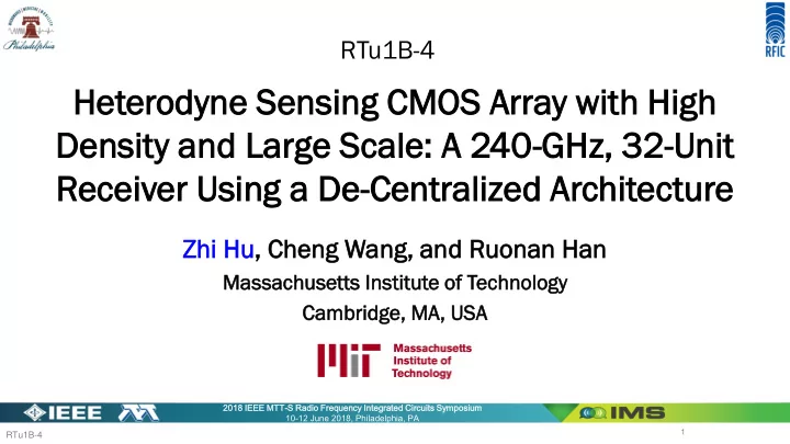
90 120 150 180 210 240 270
5 10 Measured Pattern Simulated Pattern Theta (Degree) E-Plane Antenna Directivity (dBi) 90 120 150 180 210 240 270
5 10 Measured Pattern Simulated Pattern Phi (Degree) H-Plane Antenna Directivity (dBi)
Ant Antenn enna a Pat atter ern and P n and Per erform
ance Ev Eval aluation uation
ersion sion gain (dB) CG CG = = PIF
IF – PRF RF , where
PIF
IF =
= PIF,
, analy lyzer zer – Gamp, and
PRF
RF =
= PRF, TX + + DTX
TX +
+ GRX
RX – 20log10 10(λ/(4
/(4πd))
se figure ure (dB) B) NF NF = = Pnoise
se – (-174
4 dBm) ) – CG CG, where Pnoise
ise = 10log10 10(1
(10(Pnoise
noise, , ana naly lyze zer – Gamp)/10 – 10
10-17.4
.4)
(considering NFamp = 3dB)
e Gamp = 49 dB, PRF,TX
TX =
= -7.1 1 dBm, , DTX
TX = 24 dBi,
, DRX
RX = 6.0 dB, ηRX RX = 40 % (simul
mulated), ed), λ = 1. 1.28 mm, d = 0.1 m
IF = 475 MHz (beyond
er frequ quen ency), cy), CG CG = = -42.4 dB, NF NF = 44.2 dB dB
Measu asured d and d simulat lated ed anten enna a patter erns s (E-Plane) lane) Measu asured d and d simulat lated ed anten enna a patter erns s (H-Pla lane) e)
Defin ine e Sensiti sitivi vity ty = = NEP EP ∙ √1000Hz = = -174 dBm + + NF NF + 30dB; ; for for fIF
IF = 475 MHz,
z, Sensi sitivi tivity ty = 0.10 .105 pW pW