Data Encoding Part IV : Analog to Digital Conversion Surasak - - PDF document

data encoding
SMART_READER_LITE
LIVE PREVIEW

Data Encoding Part IV : Analog to Digital Conversion Surasak - - PDF document

1/12 Data Encoding Part IV : Analog to Digital Conversion Surasak Sanguanpong nguan@ku.ac.th http://www.cpe.ku.ac.th/~nguan Last updated: 25 November 2004 Applied Network Research Group Department of Computer


slide-1
SLIDE 1

1

Applied Network Research Group Department of Computer Engineering, Kasetsart University 1/12

Data Encoding

Part IV : Analog to Digital Conversion

Surasak Sanguanpong nguan@ku.ac.th http://www.cpe.ku.ac.th/~nguan

Last updated: 25 November 2004 Applied Network Research Group Department of Computer Engineering, Kasetsart University 2/12

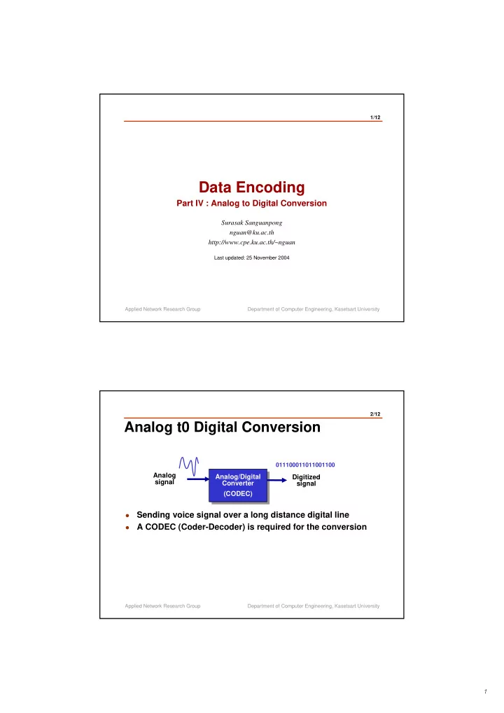
Analog t0 Digital Conversion

  • Sending voice signal over a long distance digital line
  • A CODEC (Coder-Decoder) is required for the conversion

Analog signal Analog/Digital Converter (CODEC) Analog/Digital Converter (CODEC) Digitized signal

011100011011001100

slide-2
SLIDE 2

2

Applied Network Research Group Department of Computer Engineering, Kasetsart University 3/12

Conversion Process

Analog Sampling Circuit Sampling Circuit Binary Encoding Binary Encoding Digital Encoder Encoder PCM Transmitter

  • Assign integral

values in a specific range to sample instance

Quantization Quantization A/D Converter

Sampling of analog signal with Pulse Amplitude Modulation (PAM) Technique Analog signal is converted to digital signal Binary digits are transformed into a digital signal using D to D encoding

1 2 3 4

Applied Network Research Group Department of Computer Engineering, Kasetsart University 4/12

PAM

The analog Signal is sampled at equally spaced

intervals in time

Sampling clock pulse Input signal Double-polarity PAM Single-polarity PAM

slide-3
SLIDE 3

3

Applied Network Research Group Department of Computer Engineering, Kasetsart University 5/12

Sampling Rate

  • The higher sampling rate, the closer the recovered signal

approaches the original signal.

  • Practically, voice signals are sampled at 8KHz based on the

Nyquist sampling theorem

Applied Network Research Group Department of Computer Engineering, Kasetsart University 6/12

Nyquist theorem

“ In a perfectly noiseless channel, if f is the maximum frequency the medium can transmit, the receiver can completely reconstruct a signal by sampling it 2*f times per second”

Nyquist, 1920

slide-4
SLIDE 4

4

Applied Network Research Group Department of Computer Engineering, Kasetsart University 7/12

Quantization

16 levels of quantization require 4 bits A/D converter

15 14 13 12 11 10 9 8 7 6 5 4 3 2 1

quantization level = 2 (number of A/D converter bits)

Applied Network Research Group Department of Computer Engineering, Kasetsart University 8/12

PCM sample

3.2 3.9 2.8 3.4 1.2 4.2 3 4 3 3 1 1 4 011 100 011 011 001 100 Original signal PAM pulse PCM pulse with quantized error

011100011011001100

PCM output

slide-5
SLIDE 5

5

Applied Network Research Group Department of Computer Engineering, Kasetsart University 9/12

Nonlinear encoding

1 2 3 4 5 6 7 12 13 14 15

Strong signal Weak signal

1 2 3 4 5 6 7 8 8 9 9 10 10 11 11 12 13 14 15

Without nonlinear encoding With nonlinear encoding

Applied Network Research Group Department of Computer Engineering, Kasetsart University 10/12

Companding process

  • Implement nonlinear

encoding via companding process

  • Companding =

Compressing Expanding

  • Implement nonlinear

encoding via companding process

  • Companding =

Compressing Expanding

11 10 01 00 11 10 01 00 11 10 01 00 11 10 01 00 11 10 01 00 11 10 01 00 11 10 01 00 11 10 01 00

11 10 01 00 11 10 01 00

Network Compressor circuit Compressor circuit Linear A/D Linear A/D Linear D/A Linear D/A Expander circuit Expander circuit

vi vi v’o vo

slide-6
SLIDE 6

6

Applied Network Research Group Department of Computer Engineering, Kasetsart University 11/12

Companding standard

A|Vi| 1+ ln A 1+ ln [A|Vi|] 1+ ln A ln[1 + μ |Vi|] ln[1+ μ]

1 0.8 0.6 0.4 0.2 0.2 0.4 0.6 0.8 1.0 1 0.8 0.6 0.4 0.2 0.2 0.4 0.6 0.8 1.0 Vin

Vout Vin Vout

|V0| = |V0| = A-Law (North America) μ Law (ITU-T) 0 ฃ |Vi|ฃ 1 A

ฃ |Vi|ฃ 1

1 A |V0| = 0ฃ |Vi|ฃ 1

μ=255 μ=0 μ=80 Α=100 Α=80 Α=1

Applied Network Research Group Department of Computer Engineering, Kasetsart University 12/12

PCM System

Analog voice signal Sampling Circuit Sampling Circuit A/D Converter A/D Converter Digitized voice signal Encoder Encoder Analog voice signal Regeneration Circuit Regeneration Circuit Decoder Decoder Digitized voice signal D/A Converter D/A Converter PCM Transmitter PCM Receiver