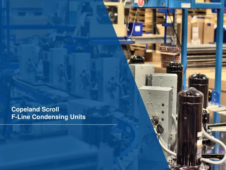

Copeland Scroll F-Line Condensing Units Presentation name (update in Slide Master)
F-Line Features • Scroll Compressors • Air & Water Cooled Condensers • Flat Metal & Copevap TM Bases • 1 to 13 HP • 1, 2 & 4 Fans • 14” to 44” Wide Applications Walk-Ins Reach-Ins Display Cases Presentation name (update in Slide Master)
Multi-Ref Chassis Explanation Example: A multi-ref unit can be operated with FFAP-020Z With ZS13KAE Compressor any refrigerant and application listed Refrigerant Capacity Condition: -10 / 120 R404A 6310 for that unit in OPI. R404A 12150 R134a 8250 Condition: 20 / 120 R22 13050 There are capacity differences R407A 12400 R407C 12100 between refrigerants and applications R404A 18050 R134a 13200 so it is important that you review Condition: 45 / 130 R22 20100 R407A 19200 electrical, mechanical and R407C 18650 performance specs prior to selecting a Condenser Sized For Largest Capacity = Chassis C 404A LT And R134a Have Significantly Less Capacity = Chassis B unit. 28.2 x 44 x 27 25.2 x 34 x 19 24 x 17.2 x 15 24 x 18.3 x 16.3 D C A B L W Presentation name (update in Slide Master)
Horsepower Does Not Guarantee An Accurate Cross Old Model Cross Options FJAL-B200 FPAK-013Z FPAK-020Z FFAP-020Z Capacity Size Cost Cross References Must Be Made By Capacity At The Operating Conditions Presentation name (update in Slide Master) Presentation name (update in Slide Master)
Multi-Ref Electrical Explanation Compressors are run at a UL specified Each refrigerant will trip at a different condition and then the voltage is current but multi-ref units must use the dropped in steps until the protector highest of all the refrigerants trips In some cases, the new models will The current where the protector trips have higher MCA and fuse size is the MCC. requirements because of this RLA = mcc / 1.4 MCA = 1.25 x (RLA + (fan amps + .3)) Presentation name (update in Slide Master)
Electronic Unit Controller Key Benefits • Quick & Easy Set-Up Key Functions • Improved Set-Point Accuracy • Controls Unit Based On Suction Pressure • Enables Multi-Refrigerant Product • Fan Cycling With Mid Coil Temperature* • Trouble Shooting Diagnostics • Discharge Line Protection* • Added System Safeguards * Feature Dependent On System Design Presentation name (update in Slide Master)
Unit Simplification Mechanical Controls Electronic Control Fan Cycling Control Temp Sensor Condenser Condenser Fan Cycling Control Temp Sensor High Pressure Discharge Switch Line T-Stat Time Delay TXV TXV Performance Alert Light Low Pressure Control Pressure Sensor Evaporator Evaporator Presentation name (update in Slide Master)
Mechanical Vs Electronics Ease Of Use – Adjusting Pressure Controls Mechanical Electronics • Fine Adjustments • Coarse Adjustments • 1.5% Accuracy Over Life • Drift Over Time Steps For Adjusting Electronic Low Pressure Control Steps For Adjusting Mech. Low Pressure Control 1. Hook Up Gage Set 1. Hold 3 Seconds To Enter Menu + (PSI Light Flashing) 2. Read System Pressure 2. Cycle Through Menu Options 3. Adjust The Mechanical Pressure 3. Control With A Wrench Or Screwdriver Select Value 4. Allow System Pressures To Settle 4. Adjust Value 5. Read System Pressures 5. Store Value 6. Final Adjustment To The Mechanical Pressure Control 7. Remove The Gage Set Up To 25 Minutes! Less Than 1 Minute! Presentation name (update in Slide Master)
Digital Temperature Display • Press The Up Arrow Button To Display The Current Condenser Temperature. • Press The Down Arrow Button To Display The Current Discharge Line Temperature. Presentation name (update in Slide Master) Presentation name (update in Slide Master)
Electronic Unit Control Service Parts • Controllers: – 115V Without Fan Cycling (943-0152-00) – 115V With Fan Cycling (943-0154-00) – 230V Without Fan Cycling (943-0153-00) – 230V With Fan Cycling (943-0155-00) • Sensors: – Low Pressure Transducer / Cable (929-0114-00) – Discharge Line Temperature Sensor (929-0113-00) – Mid Coil Temperature Sensor (929-0114-01) Important: Replacement Control Set Points Must Be Set to Match Settings Listed On Unit Label. Presentation name (update in Slide Master) Presentation name (update in Slide Master)
Information Is At Your Finger Tips In The Box On The Box On The Unit In The Unit 300-0084-00
EUC One Minute Challenge • http://emersonclimate.com/oneminutechallenge/ On-Line Simulator For Set Point And Troubleshooting Training. Presentation name (update in Slide Master)
Recommend
More recommend