Contents 5 1. General Information - - PDF document

contents
SMART_READER_LITE
LIVE PREVIEW

Contents 5 1. General Information - - PDF document

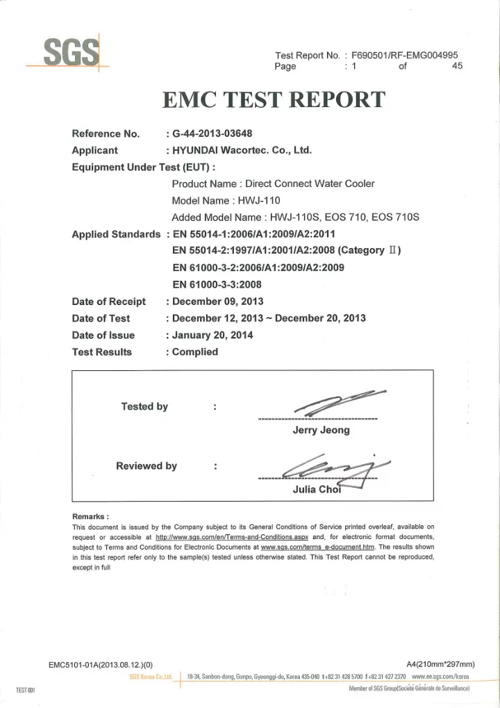
Test Report No. : F690501/RF-EMG004995 Page : 2 of 45 Contents 5 1. General Information ................................................................................................... 5 1.1 Client Information


slide-1
SLIDE 1
slide-2
SLIDE 2

Test Report No. : F690501/RF-EMG004995 Page : 2

  • f

45

EMC5101-01A(2013.08.12.)(0) A4(210mm*297mm)

Contents

  • 1. General Information

................................................................................................... 5 1.1 Client Information ................................................................................................ 5 1.2 Test Laboratory ................................................................................................... 5 1.3 General Information of E.U.T. ............................................................................. 5 1.4 Operating Modes and Conditions ........................................................................ 5 1.4.1 Monitoring Method ..................................................................................... 5 1.5 Auxiliary Equipments .......................................................................................... 6 1.6 Cable List ............................................................................................................ 6 1.7 System Configurations ........................................................................................ 6 1.8 Test System Layout ............................................................................................ 6 1.9 Modifications ....................................................................................................... 6 1.10 Applicable Standards for Testing ...................................................................... 7 1.11 Summary of Test Results .................................................................................. 7

  • 2. Emission Test

............................................................................................................ 8 2.1 Test Results ........................................................................................................ 8 2.2 Test Method and Limits ....................................................................................... 8 2.2.1 Test Method ............................................................................................... 8 2.2.2 Test Limits .................................................................................................. 8 2.3 Conducted Emission ........................................................................................... 9 2.3.1 Test Equipments ........................................................................................ 9 2.3.2 Test Site ..................................................................................................... 9 2.3.3 Environment Conditions and data ............................................................ 10 2.4 Disturbance Power ............................................................................................ 12 2.4.1 Test Equipments ...................................................................................... 12 2.4.2 Test Site ................................................................................................... 12 2.4.3 Environment Conditions and data ............................................................ 13 2.5 Photographs of Continuous Conducted Emission ............................................. 14 2.6 Photographs of Discontinuous Conducted Emission ........................................ 15 2.7 Photographs of Disturbance Power .................................................................. 15

  • 3. Harmonics & Flicker ................................................................................................

16 3.1 Test Results ...................................................................................................... 16 3.2 Test Equipments ............................................................................................... 16 3.3 Test Site ............................................................................................................ 16 3.4 Harmonics Test Data ........................................................................................ 16 3.5 Flicker Test Data ............................................................................................... 17

slide-3
SLIDE 3

Test Report No. : F690501/RF-EMG004995 Page : 3

  • f

45

EMC5101-01A(2013.08.12.)(0) A4(210mm*297mm)

3.6 Photograph of Harmonics and Flicker ............................................................... 17

  • 3. Immunity Test

.......................................................................................................... 18 3.1 Test Results ...................................................................................................... 18 3.2 Performance Criteria ......................................................................................... 18 4.3 Electrostatic Discharge ..................................................................................... 19 4.3.1 Test Equipments ...................................................................................... 19 4.3.2 Test Site ................................................................................................... 19 4.3.3 Environment Conditions ........................................................................... 19 4.3.4 Performance Criterion : B ......................................................................... 19 4.3.5 Test Points ............................................................................................... 19 4.3.6 Test Results ............................................................................................. 20 4.3.7 Test Points ............................................................................................... 21 4.3.8 Photograph of Electrostatic Discharge ..................................................... 22 4.4 Fast Transients/Burst ........................................................................................ 23 4.4.1 Test Equipments ...................................................................................... 23 4.4.2 Test Site ................................................................................................... 23 4.4.3 Environment Conditions ........................................................................... 23 4.4.4 Performance Criterion : B ......................................................................... 23 4.4.5 Test Results ............................................................................................. 23 4.4.6 Photograph of Fast Transients/Burst ....................................................... 24 4.5 Surges .............................................................................................................. 25 4.5.1 Test Equipments ...................................................................................... 25 4.5.2 Test Site ................................................................................................... 25 4.5.3 Environment Conditions ........................................................................... 25 4.5.4 Performance Criterion : B ......................................................................... 25 4.5.5 Test Results ............................................................................................. 25 4.5.6 Photograph of Surges .............................................................................. 26 4.6 Conducted Immunity Test ................................................................................. 27 4.6.1 Test Equipments ...................................................................................... 27 4.6.2 Test Site ................................................................................................... 27 4.6.3 Environment Conditions ........................................................................... 27 4.6.4 Performance Criterion : A ......................................................................... 27 4.6.5 Test Results ............................................................................................. 27 4.6.6 Photograph of Conducted Immunity ......................................................... 28 4.7 Voltage Dips and Interruptions .......................................................................... 29 4.7.1 Test Equipments ...................................................................................... 29 4.7.2 Test Site ................................................................................................... 29

slide-4
SLIDE 4

Test Report No. : F690501/RF-EMG004995 Page : 4

  • f

45

EMC5101-01A(2013.08.12.)(0) A4(210mm*297mm)

4.7.3 Environment Conditions ........................................................................... 29 4.7.4 Performance Criterion : B & C .................................................................. 29 4.7.5 Test Results ............................................................................................. 29 4.7.6 Photograph of Voltage Dips and Interruptions ......................................... 30

  • 5. Photographs of EUT

................................................................................................ 31 Appendix A : Continuous Conducted Emission ........................................................... 36 Appendix B : Discontinuous Conducted Emission ....................................................... 37 Appendix C : Disturbance Power ................................................................................. 38 Appendix D : Harmonics on AC Mains ........................................................................ 39 Appendix E : Flickers on AC Mains ............................................................................. 43

slide-5
SLIDE 5

Test Report No. : F690501/RF-EMG004995 Page : 5

  • f

45

EMC5101-01A(2013.08.12.)(0) A4(210mm*297mm)

  • 1. General Information

1.1 Client Information Applicant : HYUNDAI Wacortec. Co., Ltd. Address of Applicant : A-301, Hagye Technotown, Hagye-Dong, 10, Nowon-Ro, 15 Gil, Nowon-Gu, Seoul, Korea Manufacturer : HYUNDAI Wacortec. Co., Ltd. Address of Manufacturer : A-301, Hagye Technotown, Hagye-Dong, 10, Nowon-Ro, 15 Gil, Nowon-Gu, Seoul, Korea 1.2 Test Laboratory Name and Address : SGS Korea Co., Ltd. (Gunpo Laboratory) 4, LS-ro 182beon-gil, Gunpo-si, Gyeonggi-do, Korea Phone : + 82 31 428 5700 Fax : + 82 31 427 2370 e-mail : julia.choi@sgs.com 1.3 General Information of E.U.T. Product Name Direct Connect Water Cooler Basic Model Name HWJ-110 Added Model Names HWJ-110S, EOS 710, EOS 710S Serial No.

  • Rated Voltage

Input : 230 V a . c ., 50 ㎐ Test Voltage 230 V a . c ., 50 ㎐ Category Category Ⅱ Model Difference

  • 1. Change of Exterior : HWJ series and EOE series

have the same internal structure and apply the same electric part. The difference is only exterior as development.

  • 2. Change of Size : The difference between stand type

(HWJ-110) and desk type (HWJ-110S) is the height difference only and all electric parts are the same. 1.4 Operating Modes and Conditions Operating mode Operating condition Operating Mode Continuously flowed water 1.4.1 Monitoring Method

  • Observe any errors the supplied and drained water.
slide-6
SLIDE 6

Test Report No. : F690501/RF-EMG004995 Page : 6

  • f

45

EMC5101-01A(2013.08.12.)(0) A4(210mm*297mm)

1.5 Auxiliary Equipments Description Model Serial No. Manufacturer

  • 1.6 Cable List

Start END Cable Spec. Name I/O Port Name I/O Port Length Shield EUT AC IN AC Source

  • 1.0

Unshield 1.7 System Configurations 1.8 Test System Layout 1.9 Modifications There was no modified item during the test. Description Model Serial No. Manufacturer Main Board HD-310

  • Pump

WX30LHS5W-K D1352200226 DAEWOO ELECTRONICS Corp. Thermostat PFN-135M-04C

  • PACIFICCONTRO

LS Thermostat GNF-135SCW

  • SHINHAN

ELECTRO

slide-7
SLIDE 7

Test Report No. : F690501/RF-EMG004995 Page : 7

  • f

45

EMC5101-01A(2013.08.12.)(0) A4(210mm*297mm)

1.10 Applicable Standards for Testing 1.11 Summary of Test Results

Note : Test methods of all test items are performed according to the basic standards in this table.

Standards Status Deviation EN 55014-1:2006/A1:2009/A2:2011 Applicable No Deviation EN 55014-2:1997/A1:2001/A2:2008 (Category Ⅱ) Applicable No Deviation EN 61000-3-2:2006/A1:2009/A2:2009 Applicable No Deviation EN 61000-3-3:2008 Applicable No Deviation EN 61000-4-2:2009 Applicable No Deviation EN 61000-4-3:2006/A1:2008/A2:2010 N/A N/A EN 61000-4-4:2004/A1:2010 Applicable No Deviation EN 61000-4-5:2006 Applicable No Deviation EN 61000-4-6:2009 Applicable No Deviation EN 61000-4-11:2004 Applicable No Deviation Test Item Basic Standards Results Conducted Emission EN 55014-1:2006/A1:2009/A2:2011 Complied Disturbance Power EN 55014-1:2006/A1:2009/A2:2011 Complied Harmonics EN 61000-3-2:2006/A1:2009/A2:2009 Complied Flicker EN 61000-3-3:2008 Complied Electrostatic Discharge EN 61000-4-2:2009 Complied Radiated Immunity EN 61000-4-3:2006/A1:2008/A2:2010 N/A Fast Transients EN 61000-4-4:2004/A1:2010 Complied Surges EN 61000-4-5:2006 Complied Conducted Immunity EN 61000-4-6:2009 Complied Voltage dips and Interruptions EN 61000-4-11:2004 Complied

slide-8
SLIDE 8

Test Report No. : F690501/RF-EMG004995 Page : 8

  • f

45

EMC5101-01A(2013.08.12.)(0) A4(210mm*297mm)

EMISSION

  • 2. Emission Test

2.1 Test Results Test Items Basic Standards Test Results Conducted Emission EN 55014-1:2006/A1:2009/A2:2011 Complied Disturbance Power EN 55014-1:2006/A1:2009/A2:2011 Complied 2.2 Test Method and Limits 2.2.1 Test Method Test Items Measuring Frequency Range RBW Measuring Distance Conducted Emission 0.15 ㎒ ~ 30 ㎒ 9 ㎑ N/A Disturbance Power 30 ㎒ ~ 300 ㎒ 120 ㎑ N/A 2.2.2 Test Limits

  • Conducted Emission Limits

Frequency Range Limits( ㏈(㎶) ) Quasi-peak Average 0.15 ㎒ ~ 0.5 ㎒ 66 to 56 56 to 46 0.5 ㎒ ~ 5 ㎒ 56 46 5 ㎒ ~ 30 ㎒ 60 50

Note : The lower limit shall apply at the transition frequencies. The limit decreases linearly with the logarithm of the frequency in the range 0.15 ㎒ to 0.5 ㎒.

  • Disturbance Power Limits.

Frequency Range Limits ㏈(㎺) Quasi-peak Average 30 ㎒ ~ 300 ㎒ 45 to 55 35 to 45

Note : The limit increases linearly.

  • Margin when performing disturbance power measurement in the frequency

range 30 ㎒ to 300 ㎒. Frequency Range Limits ㏈(㎺) Quasi-peak Average 200 ㎒ ~ 300 ㎒ 0 to 10

slide-9
SLIDE 9

Test Report No. : F690501/RF-EMG004995 Page : 9

  • f

45

EMC5101-01A(2013.08.12.)(0) A4(210mm*297mm)

2.3 Conducted Emission The initial preliminary exploratory scans were performed over the measuring frequency range(0.15 ㎒ to 30 ㎒) using a max hold mode incorporating a Peak detector and Average detector and using the software of ES-K1(Version V1.71 from R&S). The final test data was measured using a Quasi-Peak detector and Average detector. 2.3.1 Test Equipments Description Model No. Manufacturer S/N Last Cal. Date Two-Line V- Network ENV216 R & S 100190 2013.01.04 Test Receiver ESHS10 R & S 863365/018 2013.06.27 Click Meter AFJ CL55C AFJ INSTRUMENTS 55041008129 2013.09.23

Note : The calibration period of every equipment is 1 year.

2.3.2 Test Site Shield Room in Gunpo Laboratory

slide-10
SLIDE 10

Test Report No. : F690501/RF-EMG004995 Page : 10

  • f

45

EMC5101-01A(2013.08.12.)(0) A4(210mm*297mm)

2.3.3 Environment Conditions and data

  • Continuous Conducted Emission

Temperature : 22.0 ℃ ~ 22.2 ℃ Humidity : 31.0 % R . H . ~ 32.0 % R . H . Atmospheric Pressure : 102.2 ㎪ Test Date : December 13, 2013

( ㎒ ) (H/N) Q/P A/V ( ㏈ ) ( ㏈ ) Q/P A/V Q/P A/V Q/P A/V 0.16 N 6.40 3.50 0.00 9.65 16.05 13.15 65.46 58.30 49.41 45.15 0.24 N 5.10 3.30 0.00 9.65 14.75 12.95 62.10 53.93 47.35 40.98 0.54 H 12.10 3.50 0.00 9.57 21.67 13.07 56.00 46.00 34.33 32.93 0.55 H 5.00 2.50 0.00 9.57 14.57 12.07 56.00 46.00 41.43 33.93 0.59 N 11.20 3.50 0.00 9.65 20.85 13.15 56.00 46.00 35.15 32.85 0.99 H 6.90 3.00 0.01 9.57 16.48 12.58 56.00 46.00 39.52 33.42 1.00 H 4.80 2.40 0.01 9.57 14.38 11.98 56.00 46.00 41.62 34.02 1.12 N 7.80 3.00 0.01 9.65 17.46 12.66 56.00 46.00 38.54 33.34 1.40 H 4.50 2.50 0.02 9.57 14.09 12.09 56.00 46.00 41.91 33.91 2.00 H 4.20 2.20 0.03 9.58 13.81 11.81 56.00 46.00 42.19 34.19 3.50 N 4.50 3.00 0.05 9.66 14.21 12.71 56.00 46.00 41.79 33.29 6.00 N 7.50 5.60 0.07 9.68 17.25 15.35 60.00 50.00 42.75 34.65 10.00 H 15.80 9.80 0.11 9.66 25.57 19.57 60.00 50.00 34.43 30.43 13.56 H 27.10 23.70 0.13 9.68 36.91 33.51 60.00 50.00 23.09 16.49 22.00 N 13.50 8.00 0.17 9.88 23.55 18.05 60.00 50.00 36.45 31.95 30.00 N 7.40 4.50 0.20 10.06 17.66 14.76 60.00 50.00 42.34 35.24 Margin ( ㏈ ) Freq. CL Level ( ㏈㎶ ) Limit ( ㏈㎶ ) Result ( ㏈㎶ ) Line LISN Measurement Uncertainty : ± 4.27 ㏈ (The confidential level is about 95%, k=2) Note :  Line ( H ) : Hot  Line ( N ) : Neutral  CL: Cable Loss  LISN : LISN Factor  Result = Level + CL + LISN  Margin = Limit – Result

See Appendix A (Continuous Conducted Emission)

slide-11
SLIDE 11

Test Report No. : F690501/RF-EMG004995 Page : 11

  • f

45

EMC5101-01A(2013.08.12.)(0) A4(210mm*297mm)

  • Discontinuous Conducted Emission

Temperature : 22.4 ℃ ~ 22.6 ℃ Humidity : 34.0 % R . H . ~ 35.0 % R . H . Atmospheric Pressure : 102.2 ㎪ Test Date : December 13, 2013 Frequency (㎒) Count (1) Click*(f)/Min N (2) Click Limit Lq=L+i Clicks (3) Limit of (4) Count Click Result 0.15 0 * 120 0.00 66 + 44 = 110 Complied 0.5 0 * 120 0.00 56 + 44 = 100 Complied 1.4 0 * 120 0.00 56 + 44 = 100 Complied 30 0 * 120 0.00 60 + 44 = 104 Complied

Measurement Uncertainty : ± 3.31 ㏈(The confidential level is about 95%, k=2)

Note : i = 44 ㏈ (N<0.2), 20log(30/N) ㏈ (0.2<N<30), 0 ㏈ (N>30) (1) First Time Test,(f)Factor (2) N = Click Rate (3) Allowed number of clicks(1/4) (4) Are the clicks above click limit (Second Test)

See Appendix B (Discontinuous Conducted Emission)

slide-12
SLIDE 12

Test Report No. : F690501/RF-EMG004995 Page : 12

  • f

45

EMC5101-01A(2013.08.12.)(0) A4(210mm*297mm)

2.4 Disturbance Power The initial preliminary exploratory scans were performed over the measuring frequency range(30 ㎒ to 300 ㎒) using a max hold mode incorporating a Peak detector and using the software of EP5RE(Version Ver3.10.20 from TOYO) with the absorbing clamp positioning at the nearest of the EUT. The final test data was measured using a Quasi-Peak detector and Average detector with the absorbing clamp moving from the EUT to the end of the clamp test table to find the maximum emitting point for each frequency. 2.4.1 Test Equipments Description Model No. Manufacturer S/N Last Cal. Date Absorbing Clamp MDS-21 R & S 100375 2013.11.11 Amplifier 8447F HP 2944A03909 2013.06.28 Test Receiver ESU26 R & S 100109 2013.02.28

Note : The calibration period of every equipment is 1 year.

2.4.2 Test Site 3 m Semi-Anechoic Chamber in Gunpo Laboratory

slide-13
SLIDE 13

Test Report No. : F690501/RF-EMG004995 Page : 13

  • f

45

EMC5101-01A(2013.08.12.)(0) A4(210mm*297mm)

2.4.3 Environment Conditions and data Temperature : 21.3 ℃ ~ 22.0 ℃ Humidity : 27.0 % R . H . ~ 28.0 % R . H . Atmospheric Pressure : 101.8 ㎪ Test Date : December 16, 2013

Freq. CF CL Amp (㎒) Q/P A/V (㏈) (㏈) (㏈) Q/P A/V Q/P A/V Q/P A/V

30.00 32.80 29.30 9.20 0.69 27.70 14.99 11.49 45.00 35.00 30.01 23.51 45.00 32.40 28.70 7.70 0.83 27.63 13.31 9.61 45.56 35.56 32.25 25.95 65.00 31.70 29.30 7.05 1.02 27.57 12.20 9.80 46.30 36.30 34.10 26.50 90.00 33.10 30.80 5.90 1.19 27.52 12.67 10.37 47.22 37.22 34.55 26.85 95.88 33.80 31.40 6.08 1.23 27.51 13.60 11.20 47.44 37.44 33.84 26.24 101.87 34.50 31.20 6.26 1.26 27.49 14.53 11.23 47.66 37.66 33.13 26.43 104.50 37.30 36.30 6.34 1.28 27.48 17.44 16.44 47.76 37.76 30.32 21.32 107.72 39.00 37.20 6.43 1.30 27.47 19.26 17.46 47.88 37.88 28.62 20.42 150.00 32.90 27.60 6.40 1.54 27.30 13.54 8.24 49.44 39.44 35.90 31.20 180.00 31.70 28.50 5.10 1.70 27.18 11.32 8.12 50.56 40.56 39.24 32.44 220.00 34.20 32.70 5.57 1.87 27.06 14.58 13.08 52.04 42.04 37.46 28.96 300.00 33.80 29.40 6.40 2.18 26.90 15.48 11.08 55.00 45.00 39.52 33.92

Result(㏈㎺) Limit(㏈㎺) Margin(㏈) Level(㏈㎶)

Measurement Uncertainty : ± 2.59 ㏈ (The confidential level is about 95%, k=2) Note :  Margin = Limit – Result  CF : Clamp Factor  Amp : Amplifier Gain  CL : Cable Loss  Result = Level + CF + CL – Amp

See Appendix C (Disturbance Power)

slide-14
SLIDE 14

Test Report No. : F690501/RF-EMG004995 Page : 14

  • f

45

EMC5101-01A(2013.08.12.)(0) A4(210mm*297mm)

2.5 Photographs of Continuous Conducted Emission

slide-15
SLIDE 15

Test Report No. : F690501/RF-EMG004995 Page : 15

  • f

45

EMC5101-01A(2013.08.12.)(0) A4(210mm*297mm)

2.6 Photographs of Discontinuous Conducted Emission 2.7 Photographs of Disturbance Power

slide-16
SLIDE 16

Test Report No. : F690501/RF-EMG004995 Page : 16

  • f

45

EMC5101-01A(2013.08.12.)(0) A4(210mm*297mm)

Harmonics & Flicker

  • 3. Harmonics & Flicker

3.1 Test Results Test Items Standards Test Results Harmonics EN 61000-3-2 :2006/A1:2009/A2:2009 Complied Flicker EN 61000-3-3 :2008 Complied 3.2 Test Equipments Equipment Model Manufacturer S/N Last Cal. Date H/F Analyzer DPA 500 EM TEST V0508100155 2013.04.11 AC Source ACS 500 EM TEST V0508100156 2013.04.11

Note : The calibration period of every equipment is 1 year.

3.3 Test Site Harmonics & Flicker Site in Gunpo Laboratory 3.4 Harmonics Test Data The measurement was conducted with an automatic harmonics analyzing system, Measured were all harmonics up to order 40. Temperature 22.3 ℃ ~ 22.4 ℃ Humidity : 25.0 % R . H . Atmospheric Pressure : 101.8 ㎪ Test Date : December 12, 2013 See Appendix C (Harmonics on AC Mains)

slide-17
SLIDE 17

Test Report No. : F690501/RF-EMG004995 Page : 17

  • f

45

EMC5101-01A(2013.08.12.)(0) A4(210mm*297mm)

3.5 Flicker Test Data The measurement was conducted with an automatic flicker system, Measured were all Flicker up to order 12. Temperature 22.4 ℃ ~ 23.5 ℃ Humidity : 25.0 % R . H . ~ 28.0 % R . H . Atmospheric Pressure : 101.8 ㎪ Test Date : December 12, 2013 See Appendix D (Flicker on AC Mains) 3.6 Photograph of Harmonics and Flicker

slide-18
SLIDE 18

Test Report No. : F690501/RF-EMG004995 Page : 18

  • f

45

EMC5101-01A(2013.08.12.)(0) A4(210mm*297mm)

IMMUNITY

  • 3. Immunity Test

3.1 Test Results Test Items Basic Standards Test Results Electrostatic Discharge EN 61000-4-2:2009 Complied Fast Transients/Burst EN 61000-4-4:2004/A1:2010 Complied Surges EN 61000-4-5:2006 Complied Conducted Immunity EN 61000-4-6:2009 Complied Voltage dips and Interruptions EN 61000-4-11:2004 Complied 3.2 Performance Criteria Criterion A - The equipment shall continue to operate as intended without operator

  • intervention. No degradation of performance or loss of function is allowed below a

performance level specified by the manufacturer when the equipment is used as intended. Criterion B - After the test, the equipment shall continue to operate as intended without operator intervention. No degradation of performance or loss of function is allowed, after the application of the phenomena below a performance level specified by the manufacturer, when the equipment is used as intended. During the test, degradation of performance is allowed. However no change of operating state or stored data is allowed to persist after the test. Criterion C - Loss of function is allowed, provided the function is self-recoverable, or can be restored by the operation of the controls by the user in accordance with the manufacturer’s instructions. Functions, and/or information stored in non-volatile memory, or protected by a battery backup, shall not be lost.

slide-19
SLIDE 19

Test Report No. : F690501/RF-EMG004995 Page : 19

  • f

45

EMC5101-01A(2013.08.12.)(0) A4(210mm*297mm)

4.3 Electrostatic Discharge 4.3.1 Test Equipments Description Model Manufacturer S/N Last Cal. Date ESD Simulator ESS-2000 NoiseKen ESS0746780 2013.01.28 VCP N/A

  • Note : The calibration period of every equipment is 1 year.

4.3.2 Test Site Shield Room in Gunpo Laboratory 4.3.3 Environment Conditions Temperature : 22.0 ℃ ~ 22.1 ℃ Humidity : 34.0 % R . H . ~ 35.0 % R . H . Atmospheric Pressure : 101.6 ㎪ Test Date : December 20, 2013 4.3.4 Performance Criterion : B 4.3.5 Test Points No. Test Points No. Test Points 1 Screw 5 Lever 2 Enclosure 6 Switch 3 Enclosure 7 VCP 4 LED

slide-20
SLIDE 20

Test Report No. : F690501/RF-EMG004995 Page : 20

  • f

45

EMC5101-01A(2013.08.12.)(0) A4(210mm*297mm)

4.3.6 Test Results Direct Application

  • No. Discharge

Method Number of Discharge Level( ㎸) Results +2

  • 2

+4

  • 4

+6

  • 6

+8

  • 8

1 Contact ≥10 times

  • A

A

  • Complied

2 Contact ≥10 times

  • A

A

  • Complied

3 Air ≥10 times

  • A

A Complied 4 Air ≥10 times

  • A

A Complied 5 Air ≥10 times

  • A

A Complied 6 Air ≥10 times

  • A

A Complied Indirect Application

  • No. Discharge

Method Number of Discharge Level( ㎸) Results +2

  • 2

+4

  • 4

+6

  • 6

+8

  • 8

7 Contact ≥10 times

  • A

A

  • Complied

Performance Criteria A, the EUT normally operates during and after the test.

Note : This product was tested for VCP only.

slide-21
SLIDE 21

Test Report No. : F690501/RF-EMG004995 Page : 21

  • f

45

EMC5101-01A(2013.08.12.)(0) A4(210mm*297mm)

4.3.7 Test Points

  • Front View
  • Rear View

Contact Air

3 5 2 4 3 1 6

slide-22
SLIDE 22

Test Report No. : F690501/RF-EMG004995 Page : 22

  • f

45

EMC5101-01A(2013.08.12.)(0) A4(210mm*297mm)

4.3.8 Photograph of Electrostatic Discharge

slide-23
SLIDE 23

Test Report No. : F690501/RF-EMG004995 Page : 23

  • f

45

EMC5101-01A(2013.08.12.)(0) A4(210mm*297mm)

4.4 Fast Transients/Burst 4.4.1 Test Equipments Description Model No. Manufacturer S/N Last Cal. Date Motion Driven AC Source MV2616 EM TEST V0508100161 2013.06.17 Ultra-Compact Simulator UCS 500-M EM TEST V0508100159 2013.06.17

Note : The calibration period of every equipment is 1 year.

4.4.2 Test Site Immunity Test Site in Gunpo Laboratory 4.4.3 Environment Conditions Temperature : 21.1 ℃ ~ 21.2 ℃ Humidity : 27.0 % R . H . ~ 28.0 % R . H . Atmospheric Pressure : 101.8 ㎪ Test Date : December 18, 2013 4.4.4 Performance Criterion : B 4.4.5 Test Results Test Point Polarity Coupling Repetition Pulse ( ㎱) Duration Test Level ( ㎸) Results L1+L2+PE +/- Direct 5 ㎑ 5/50 ≥ 2 mi n 1.0 Complied Performance Criteria A, the EUT normally operates during and after the test.

slide-24
SLIDE 24

Test Report No. : F690501/RF-EMG004995 Page : 24

  • f

45

EMC5101-01A(2013.08.12.)(0) A4(210mm*297mm)

4.4.6 Photograph of Fast Transients/Burst

slide-25
SLIDE 25

Test Report No. : F690501/RF-EMG004995 Page : 25

  • f

45

EMC5101-01A(2013.08.12.)(0) A4(210mm*297mm)

4.5 Surges 4.5.1 Test Equipments Description Model No. Manufacturer S/N Last Cal. Date Motion Driven AC Source MV2616 EM TEST V0508100161 2013.06.17 Ultra-Compact Simulator UCS 500-M EM TEST V0508100159 2013.06.17

Note : The calibration period of every equipment is 1 year.

4.5.2 Test Site Immunity Test Site in Gunpo Laboratory 4.5.3 Environment Conditions Temperature : 21.2 ℃ ~ 21.5 ℃ Humidity : 28.0 % R . H . ~ 29.0 % R . H . Atmospheric Pressure : 101.8 ㎪ Test Date : December 18, 2013 4.5.4 Performance Criterion : B 4.5.5 Test Results Test Point Polarity Coupling Pulse ( ㎲) Number

  • f

Surges Repetition Phase Angle(˚) Test Level ( ㎸) Results L1+L2 +/- Direct 1.2/50 5 ≤ 60 s 90, 270 1.0 Complied L1+PE +/- Direct 1.2/50 5 ≤ 60 s 90, 270 2.0 Complied L2+PE +/- Direct 1.2/50 5 ≤ 60 s 90, 270 2.0 Complied Performance Criteria A, the EUT normally operates during and after the test.

slide-26
SLIDE 26

Test Report No. : F690501/RF-EMG004995 Page : 26

  • f

45

EMC5101-01A(2013.08.12.)(0) A4(210mm*297mm)

4.5.6 Photograph of Surges

slide-27
SLIDE 27

Test Report No. : F690501/RF-EMG004995 Page : 27

  • f

45

EMC5101-01A(2013.08.12.)(0) A4(210mm*297mm)

4.6 Conducted Immunity Test 4.6.1 Test Equipments Description Model No. Manufacturer S/N Last Cal. Date CDN FCC-801-M3- 16A FCC 04002 2013.09.26 Amplifier 150A250 AR 312201 2013.01.06 Dual Directional Coupler DC2600M2 AR 311978 2013.01.06 Signal Generator SML03 R & S 102135 2013.01.03 Voltage Sensor URV5-Z2 R & S 100234, 100235 2013.01.04 Milli voltmeter URV5 R & S 100240 2013.01.04 Attenuator 300-A-FFN-06 BIRD Electronics Corporation 0433 2013.01.06

Note : The calibration period of every equipment is 1 year.

4.6.2 Test Site Immunity Test Site in Gunpo Laboratory 4.6.3 Environment Conditions Temperature : 21.4 ℃ ~ 21.6 ℃ Humidity : 26.0 % R . H . ~ 27.0 % R . H . Atmospheric Pressure : 100.2 ㎪ Test Date : December 19, 2013 4.6.4 Performance Criterion : A 4.6.5 Test Results Frequency ( ㎒) Test Point Coupling Voltage Level Modulation Frequency Step Dwell Time Results 0.15 ~ 230 AC IN CDN 3 V 80% AM(1 ㎑) 1 % 3 s Complied Performance Criteria A, the EUT normally operates during and after the test.

slide-28
SLIDE 28

Test Report No. : F690501/RF-EMG004995 Page : 28

  • f

45

EMC5101-01A(2013.08.12.)(0) A4(210mm*297mm)

4.6.6 Photograph of Conducted Immunity

slide-29
SLIDE 29

Test Report No. : F690501/RF-EMG004995 Page : 29

  • f

45

EMC5101-01A(2013.08.12.)(0) A4(210mm*297mm)

4.7 Voltage Dips and Interruptions 4.7.1 Test Equipments Description Model No. Manufacturer S/N Last Cal. Date Motion Driven AC Source MV2616 EM TEST V0508100161 2013.06.17 Ultra-Compact Simulator UCS 500-M EM TEST V0508100159 2013.06.17

Note : The calibration period of every equipment is 1 year.

4.7.2 Test Site Immunity Test Site in Gunpo Laboratory 4.7.3 Environment Conditions Temperature : 22.0 ℃ ~ 22.1 ℃ Humidity : 28.0 % R . H . Atmospheric Pressure : 101.8 ㎪ Test Date : December 18, 2013 4.7.4 Performance Criterion : B & C 4.7.5 Test Results Test Level % UT Voltage Dip/Int. % UT Duration ㎳/Cycle Results 0 % 100 % 0.5Cycle Complied 40 % 60 % 10 Cycle (50 ㎐), 12 Cycle (60 ㎐) Complied 70 % 30 % 25 Cycle (50 ㎐), 30 Cycle (60 ㎐) Complied Performance Criteria A, the LED of EUT flickered during the test. But after the test, the EUT normally operated.

slide-30
SLIDE 30

Test Report No. : F690501/RF-EMG004995 Page : 30

  • f

45

EMC5101-01A(2013.08.12.)(0) A4(210mm*297mm)

4.7.6 Photograph of Voltage Dips and Interruptions

slide-31
SLIDE 31

Test Report No. : F690501/RF-EMG004995 Page : 31

  • f

45

EMC5101-01A(2013.08.12.)(0) A4(210mm*297mm)

  • 5. Photographs of EUT

 Front View  Rear View

slide-32
SLIDE 32

Test Report No. : F690501/RF-EMG004995 Page : 32

  • f

45

EMC5101-01A(2013.08.12.)(0) A4(210mm*297mm)

 Top View of Main Board  Bottom View of Main Board

slide-33
SLIDE 33

Test Report No. : F690501/RF-EMG004995 Page : 33

  • f

45

EMC5101-01A(2013.08.12.)(0) A4(210mm*297mm)

 Pump  Pump Label

slide-34
SLIDE 34

Test Report No. : F690501/RF-EMG004995 Page : 34

  • f

45

EMC5101-01A(2013.08.12.)(0) A4(210mm*297mm)

 Thermostat  Thermostat Label

slide-35
SLIDE 35

Test Report No. : F690501/RF-EMG004995 Page : 35

  • f

45

EMC5101-01A(2013.08.12.)(0) A4(210mm*297mm)

 Inside

slide-36
SLIDE 36

Test Report No. : F690501/RF-EMG004995 Page : 36

  • f

45

EMC5101-01A(2013.08.12.)(0) A4(210mm*297mm)

Appendix A : Continuous Conducted Emission Neutral Hot

20 40 60 80 100 Level [dBµV] 150k 300k 500k 1M 2M 3M 5M 7M 10M 30M Frequency [Hz] 20 40 60 80 100 Level [dBµV] 150k 300k 500k 1M 2M 3M 5M 7M 10M 30M Frequency [Hz]

slide-37
SLIDE 37

Test Report No. : F690501/RF-EMG004995 Page : 37

  • f

45

EMC5101-01A(2013.08.12.)(0) A4(210mm*297mm)

Appendix B : Discontinuous Conducted Emission

slide-38
SLIDE 38

Test Report No. : F690501/RF-EMG004995 Page : 38

  • f

45

EMC5101-01A(2013.08.12.)(0) A4(210mm*297mm)

Appendix C : Disturbance Power

slide-39
SLIDE 39

Test Report No. : F690501/RF-EMG004995 Page : 39

  • f

45

EMC5101-01A(2013.08.12.)(0) A4(210mm*297mm)

Appendix D : Harmonics on AC Mains

Standard used: EN/IEC 61000-3-2 Ed.3 Quasi-stationary Equipment class A <= 150% of the limit Observation time: 150s Test Result

  • E. U. T.:

PASS Power Source: PASS

E E. . U U. . T T. . R Re es su ul lt t

Check harmonics 2..40 [exception odd 21..39]:

Harmonic(s) > 150%: Order (n): None Harmonic(s) with average > 100%: Order (n): None

Check odd harmonics 21..39:

All Partial Odd Harmonics below partial limits. Harmonic(s) > 150%: Order (n): None Harmonic(s) with average > 150%: Order (n): None

P Po

  • w

we er r S So

  • u

ur rc ce e R Re es su ul lt t

First dataset out of limit: DS (time): None Harmonic(s) out of limit: Order (n): None

slide-40
SLIDE 40

Test Report No. : F690501/RF-EMG004995 Page : 40

  • f

45

EMC5101-01A(2013.08.12.)(0) A4(210mm*297mm)

Average harmonic current results

Hn Ieff [A] % of Limit Limit [A] Result 1 2.669 2 13.428E-3 1.243 1.08 PASS 3 25.682E-3 1.117 2.30 PASS 4 3.726E-3 0.866 430.00E-3 PASS 5 15.664E-3 1.374 1.14 PASS 6 1.433E-3 0.478 300.00E-3 PASS 7 5.090E-3 0.661 770.00E-3 PASS 8 1.011E-3 0.440 230.00E-3 PASS 9 3.423E-3 0.856 400.00E-3 PASS 10 932.190E-6 0.507 184.00E-3 PASS 11 1.779E-3 0.539 330.00E-3 PASS 12 843.506E-6 0.550 153.33E-3 PASS 13 1.193E-3 0.568 210.00E-3 PASS 14 1.127E-3 0.858 131.43E-3 PASS 15 877.938E-6 0.585 150.00E-3 PASS 16 801.782E-6 0.697 115.00E-3 PASS 17 1.269E-3 0.959 132.35E-3 PASS 18 1.152E-3 1.127 102.22E-3 PASS 19 934.606E-6 0.789 118.42E-3 PASS 20 798.803E-6 0.868 92.00E-3 PASS 21 967.859E-6 0.602 160.71E-3 PASS 22 980.327E-6 1.172 83.64E-3 PASS 23 1.063E-3 0.724 146.74E-3 PASS 24 854.396E-6 1.115 76.66E-3 PASS 25 901.711E-6 0.668 135.00E-3 PASS 26 967.712E-6 1.367 70.77E-3 PASS 27 1.081E-3 0.865 124.99E-3 PASS 28 1.168E-3 1.777 65.71E-3 PASS 29 1.033E-3 0.887 116.39E-3 PASS 30 1.005E-3 1.639 61.33E-3 PASS 31 968.981E-6 0.890 108.87E-3 PASS 32 946.985E-6 1.647 57.50E-3 PASS 33 917.857E-6 0.897 102.27E-3 PASS 34 802.614E-6 1.483 54.12E-3 PASS 35 814.030E-6 0.844 96.44E-3 PASS 36 930.899E-6 1.821 51.11E-3 PASS 37 986.613E-6 1.082 91.21E-3 PASS 38 798.625E-6 1.649 48.42E-3 PASS 39 785.859E-6 0.908 86.53E-3 PASS 40 818.931E-6 1.780 46.00E-3 PASS

slide-41
SLIDE 41

Test Report No. : F690501/RF-EMG004995 Page : 41

  • f

45

EMC5101-01A(2013.08.12.)(0) A4(210mm*297mm)

Maximum harmonic current results

Hn Ieff [A] % of Limit Limit [A] Result 1 2.671 2 13.612E-3 0.840 1.62 PASS 3 26.284E-3 0.762 3.45 PASS 4 4.057E-3 0.629 645.00E-3 PASS 5 16.084E-3 0.941 1.71 PASS 6 1.542E-3 0.343 450.00E-3 PASS 7 5.325E-3 0.461 1.15 PASS 8 1.114E-3 0.323 345.00E-3 PASS 9 3.899E-3 0.650 600.00E-3 PASS 10 1.025E-3 0.371 276.00E-3 PASS 11 1.916E-3 0.387 495.00E-3 PASS 12 935.194E-6 0.407 229.99E-3 PASS 13 1.485E-3 0.471 315.00E-3 PASS 14 1.321E-3 0.670 197.15E-3 PASS 15 969.982E-6 0.431 225.00E-3 PASS 16 882.413E-6 0.512 172.50E-3 PASS 17 1.367E-3 0.689 198.52E-3 PASS 18 1.281E-3 0.836 153.33E-3 PASS 19 1.041E-3 0.586 177.63E-3 PASS 20 906.459E-6 0.657 138.00E-3 PASS 21 1.074E-3 0.668 160.71E-3 PASS 22 1.171E-3 0.934 125.46E-3 PASS 23 1.254E-3 0.854 146.74E-3 PASS 24 926.256E-6 0.806 114.99E-3 PASS 25 996.142E-6 0.738 135.00E-3 PASS 26 1.083E-3 1.020 106.16E-3 PASS 27 1.199E-3 0.959 124.99E-3 PASS 28 1.328E-3 1.347 98.57E-3 PASS 29 1.122E-3 0.964 116.39E-3 PASS 30 1.093E-3 1.188 92.00E-3 PASS 31 1.141E-3 1.048 108.87E-3 PASS 32 1.080E-3 1.252 86.25E-3 PASS 33 1.004E-3 0.982 102.27E-3 PASS 34 893.101E-6 1.100 81.18E-3 PASS 35 889.798E-6 0.923 96.44E-3 PASS 36 1.057E-3 1.379 76.66E-3 PASS 37 1.126E-3 1.234 91.21E-3 PASS 38 893.770E-6 1.231 72.63E-3 PASS 39 871.942E-6 1.008 86.53E-3 PASS 40 932.809E-6 1.352 69.00E-3 PASS

slide-42
SLIDE 42

Test Report No. : F690501/RF-EMG004995 Page : 42

  • f

45

EMC5101-01A(2013.08.12.)(0) A4(210mm*297mm)

Maximum harmonic voltage results

Hn Ueff [V] Ueff [%] Limit [%] Result 1 231.52 100.663 2 76.02E-3 0.033 0.2 PASS 3 94.47E-3 0.041 0.9 PASS 4 22.04E-3 0.010 0.2 PASS 5 52.85E-3 0.023 0.4 PASS 6 14.61E-3 0.006 0.2 PASS 7 49.28E-3 0.021 0.3 PASS 8 18.72E-3 0.008 0.2 PASS 9 66.15E-3 0.029 0.2 PASS 10 31.88E-3 0.014 0.2 PASS 11 61.02E-3 0.027 0.1 PASS 12 21.93E-3 0.010 0.1 PASS 13 73.93E-3 0.032 0.1 PASS 14 25.99E-3 0.011 0.1 PASS 15 60.15E-3 0.026 0.1 PASS 16 18.71E-3 0.008 0.1 PASS 17 73.44E-3 0.032 0.1 PASS 18 26.32E-3 0.011 0.1 PASS 19 56.01E-3 0.024 0.1 PASS 20 21.04E-3 0.009 0.1 PASS 21 72.40E-3 0.031 0.1 PASS 22 24.61E-3 0.011 0.1 PASS 23 54.06E-3 0.024 0.1 PASS 24 23.58E-3 0.010 0.1 PASS 25 69.27E-3 0.030 0.1 PASS 26 28.76E-3 0.013 0.1 PASS 27 48.11E-3 0.021 0.1 PASS 28 17.84E-3 0.008 0.1 PASS 29 73.46E-3 0.032 0.1 PASS 30 30.99E-3 0.013 0.1 PASS 31 43.85E-3 0.019 0.1 PASS 32 18.44E-3 0.008 0.1 PASS 33 70.77E-3 0.031 0.1 PASS 34 25.80E-3 0.011 0.1 PASS 35 34.10E-3 0.015 0.1 PASS 36 21.72E-3 0.009 0.1 PASS 37 68.67E-3 0.030 0.1 PASS 38 21.56E-3 0.009 0.1 PASS 39 22.93E-3 0.010 0.1 PASS 40 20.23E-3 0.009 0.1 PASS

slide-43
SLIDE 43

Test Report No. : F690501/RF-EMG004995 Page : 43

  • f

45

EMC5101-01A(2013.08.12.)(0) A4(210mm*297mm)

Appendix E : Flickers on AC Mains

M Ma ax xi im mu um m F Fl li ic ck ke er r r re es su ul lt ts s

EUT values Limit Result Pst 0.273 1.00 PASS Plt 0.122 0.65 PASS dc [%] 0.411 3.30 PASS dmax [%] 1.590 4.00 PASS dt [s] 0.000 0.50 PASS

D De et ta ai il l F Fl li ic ck ke er r d da at ta a

Flicker measurement 1 EUT values Limit Result Pst 0.066 1.00 PASS dc [%] 0.409 3.30 PASS dmax [%] 0.440 4.00 PASS dt [s] 0.000 0.50 PASS Flicker measurement 2 EUT values Limit Result Pst 0.028 1.00 PASS dc [%] 0.000 3.30 PASS dmax [%] 0.035 4.00 PASS dt [s] 0.000 0.50 PASS Flicker measurement 3 EUT values Limit Result Pst 0.028 1.00 PASS dc [%] 0.000 3.30 PASS dmax [%] 0.040 4.00 PASS dt [s] 0.000 0.50 PASS

slide-44
SLIDE 44

Test Report No. : F690501/RF-EMG004995 Page : 44

  • f

45

EMC5101-01A(2013.08.12.)(0) A4(210mm*297mm)

Flicker measurement 4 EUT values Limit Result Pst 0.096 1.00 PASS dc [%] 0.411 3.30 PASS dmax [%] 0.448 4.00 PASS dt [s] 0.000 0.50 PASS Flicker measurement 5 EUT values Limit Result Pst 0.273 1.00 PASS dc [%] 0.407 3.30 PASS dmax [%] 1.590 4.00 PASS dt [s] 0.000 0.50 PASS Flicker measurement 6 EUT values Limit Result Pst 0.028 1.00 PASS dc [%] 0.000 3.30 PASS dmax [%] 0.038 4.00 PASS dt [s] 0.000 0.50 PASS Flicker measurement 7 EUT values Limit Result Pst 0.037 1.00 PASS dc [%] 0.158 3.30 PASS dmax [%] 0.198 4.00 PASS dt [s] 0.000 0.50 PASS Flicker measurement 8 EUT values Limit Result Pst 0.028 1.00 PASS dc [%] 0.000 3.30 PASS dmax [%] 0.037 4.00 PASS dt [s] 0.000 0.50 PASS

slide-45
SLIDE 45

Test Report No. : F690501/RF-EMG004995 Page : 45

  • f

45

EMC5101-01A(2013.08.12.)(0) A4(210mm*297mm)

Flicker measurement 9 EUT values Limit Result Pst 0.028 1.00 PASS dc [%] 0.000 3.30 PASS dmax [%] 0.038 4.00 PASS dt [s] 0.000 0.50 PASS Flicker measurement 10 EUT values Limit Result Pst 0.028 1.00 PASS dc [%] 0.000 3.30 PASS dmax [%] 0.035 4.00 PASS dt [s] 0.000 0.50 PASS Flicker measurement 11 EUT values Limit Result Pst 0.028 1.00 PASS dc [%] 0.000 3.30 PASS dmax [%] 0.034 4.00 PASS dt [s] 0.000 0.50 PASS Flicker measurement 12 EUT values Limit Result Pst 0.028 1.00 PASS dc [%] 0.000 3.30 PASS dmax [%] 0.034 4.00 PASS dt [s] 0.000 0.50 PASS