Computer Architectures Changing Definition Appendix B 1950s to - - PDF document

computer architecture s changing definition
SMART_READER_LITE
LIVE PREVIEW

Computer Architectures Changing Definition Appendix B 1950s to - - PDF document

Computer Architectures Changing Definition Appendix B 1950s to 1960s: Computer Architecture Course = Computer Arithmetic 1970s to mid 1980s: Instruction Set Principles Instruction Set Principles Computer Architecture Course =


slide-1
SLIDE 1

1 Appendix B Instruction Set Principles Instruction Set Principles and Examples

1

Computer Architecture’s Changing Definition

  • 1950s to 1960s:

Computer Architecture Course = Computer Arithmetic

  • 1970s to mid 1980s:

Computer Architecture Course = Instruction Set Design, especially ISA appropriate for compilers

  • 1990s:

Computer Architecture Course = Design of CPU, memory system, I/O system, Multiprocessors

2

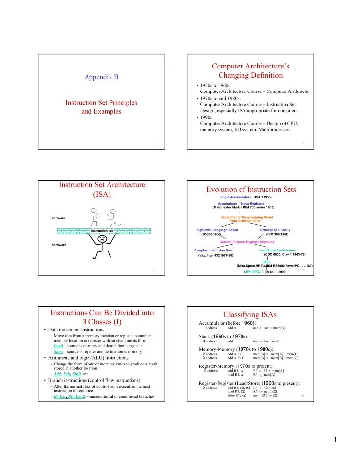
Instruction Set Architecture (ISA)

software instruction set hardware

3

Evolution of Instruction Sets

Single Accumulator (EDSAC 1950) Accumulator + Index Registers (Manchester Mark I, IBM 700 series 1953) Separation of Programming Model from Implementation High-level Language Based Concept of a Family (B5000 1963) (IBM 360 1964) General Purpose Register Machines Complex Instruction Sets Load/Store Architecture RISC (Vax, Intel 432 1977-80) (CDC 6600, Cray 1 1963-76) (Mips,Sparc,HP-PA,IBM RS6000,PowerPC . . .1987) LIW/”EPIC”? (IA-64. . .1999)

4

Instructions Can Be Divided into 3 Classes (I)

  • Data movement instructions

– Move data from a memory location or register to another memory location or register without changing its form – Load—source is memory and destination is register – Store—source is register and destination is memory

  • Arithmetic and logic (ALU) instructions

– Change the form of one or more operands to produce a result stored in another location – Add, Sub, Shift, etc.

  • Branch instructions (control flow instructions)

– Alter the normal flow of control from executing the next instruction in sequence – Br Loc, Brz Loc2,—unconditional or conditional branches

5

Classifying ISAs

Accumulator (before 1960):

1 address add A acc <− acc + mem[A]

Stack (1960s to 1970s):

0 address add tos <− tos + next

Memory-Memory (1970s to 1980s):

2 address add A B mem[A] < mem[A] + mem[B] 2 address add A, B mem[A] <− mem[A] + mem[B] 3 address add A, B, C mem[A] <− mem[B] + mem[C]

Register-Memory (1970s to present):

2 address add R1, A R1 <− R1 + mem[A] load R1, A R1 <_ mem[A]

Register-Register (Load/Store) (1960s to present):

3 address add R1, R2, R3 R1 <− R2 + R3 load R1, R2 R1 <− mem[R2] store R1, R2 mem[R1] <− R2

6

slide-2
SLIDE 2

2

Classifying ISAs

7

Load-Store Architectures

  • Instruction set:

add R1, R2, R3 sub R1, R2, R3 mul R1, R2, R3 load R1, R4 store R1, R4

  • Example: A*B - (A+C*B)

load R1, &A load R2, &B load R3, &C load R4, R1 load R5, R2 load R6, R3 mul R7, R6, R5 /* C*B */ add R8, R7, R4 /* A + C*B */ mul R9, R4, R5 /* A*B */ sub R10, R9, R8 /* A*B - (A+C*B) */

8

Load-Store: Pros and Cons

  • Pros

– Simple, fixed length instruction encoding – Instructions take similar number of cycles R l ti l t i li – Relatively easy to pipeline

  • Cons

– Higher instruction count – Not all instructions need three operands – Dependent on good compiler

9

Registers: Advantages and Disadvantages

  • Advantages

– Faster than cache (no addressing mode or tags) – Deterministic (no misses) – Can replicate (multiple read ports) – Short identifier (typically 3 to 8 bits) – Reduce memory traffic

  • Disadvantages

– Need to save and restore on procedure calls and context switch – Can’t take the address of a register (for pointers) – Fixed size (can’t store strings or structures efficiently) – Compiler must manage

10

General Register Machine and Instruction Formats

Memory Op1Addr: Op1 load load R8, Op1 (R8 <− Op1) CPU Registers R8 R6 Instruction formats R8 load Op1Addr Nexti Program counter R4 R2 add R2, R4, R6 (R2 <− R4 + R6) R2 add R6 R4

11

  • It is the most common choice in today’s

general-purpose computers

  • Which register is specified by small

General Register Machine and Instruction Formats

g p y “address” (3 to 6 bits for 8 to 64 registers)

  • Load and store have one long & one short

address: One and half addresses

  • Arithmetic instruction has 3 “half”

addresses

12

slide-3
SLIDE 3

3

Real Machines Are Not So Simple

  • Most real machines have a mixture of 3, 2, 1, 0,

and 1- address instructions

  • A distinction can be made on whether arithmetic

instructions use data from memory instructions use data from memory

  • If ALU instructions only use registers for
  • perands and result, machine type is load-store

– Only load and store instructions reference memory

  • Other machines have a mix of register-memory

and memory-memory instructions

13

Alignment Issues

  • If the architecture does not restrict memory accesses to be

aligned then

– Software is simple – Hardware must detect misalignment and make 2 memory accesses – Expensive detection logic is required – All references can be made slower

  • Sometimes unrestricted alignment is required for backwards

compatibility compatibility

  • If the architecture restricts memory accesses to be aligned then

– Software must guarantee alignment – Hardware detects misalignment access and traps – No extra time is spent when data is aligned

  • Since we want to make the common case fast, having restricted

alignment is often a better choice, unless compatibility is an issue

14

Types of Addressing Modes (VAX)

1.Register direct Ri 2.Immediate (literal) #n 3.Displacement M[Ri + #n] 4.Register indirect M[Ri] 5 Indexed M[Ri + Rj]

memory

5.Indexed M[Ri + Rj] 6.Direct (absolute) M[#n] 7.Memory IndirectM[M[Ri] ] 8.Autoincrement M[Ri++] 9.Autodecrement M[Ri - -]

  • 10. Scaled

M[Ri + Rj*d + #n]

  • reg. file

15

Summary of Use of Addressing Modes

16

Distribution of Displacement Values

17

Frequency of Immediate Operands

18

slide-4
SLIDE 4

4

Types of Operations

  • Arithmetic and Logic: AND, ADD
  • Data Transfer:

MOVE, LOAD, STORE

  • Control

BRANCH, JUMP, CALL , ,

  • System

OS CALL, VM

  • Floating Point

ADDF, MULF, DIVF

  • Decimal

ADDD, CONVERT

  • String

MOVE, COMPARE

  • Graphics

(DE)COMPRESS

19

Distribution of Data Accesses by Size

20

80x86 Instruction Frequency (SPECint92, Fig. B.13)

Rank Instruction Frequency 1 load 22% 2 branch 20% 3 compare 16% 4 store 12% 5 add 8% 6 and 6% 7 sub 5% 8 register move 4%

9

9 call 1% 10 return 1% Total 96%

21

Relative Frequency of Control Instructions

22

Control instructions (cont’d)

  • Addressing modes

– PC-relative addressing (independent of program load & displacements are close by)

R i di l t (h bit ?)

  • Requires displacement (how many bits?)
  • Determined via empirical study. [8-16 works!]

– For procedure returns/indirect jumps/kernel traps, target may not be known at compile time.

  • Jump based on contents of register
  • Useful for switch/(virtual) functions/function ptrs/dynamically

linked libraries etc.

23

Branch Distances (in terms of number of instructions)

24

slide-5
SLIDE 5

5

Frequency of Different Types of Compares in Conditional Branches

25

Encoding an Instruction set

  • a desire to have as many registers and

addressing mode as possible

  • the impact of size of register and addressing

p g g mode fields on the average instruction size and hence on the average program size

  • a desire to have instruction encode into

lengths that will be easy to handle in the implementation

26

Three choice for encoding the instruction set

27

Compilers and ISA

  • Compiler Goals

– All correct programs compile correctly – Most compiled programs execute quickly – Most programs compile quickly – Achieve small code size – Provide debugging support

  • Multiple Source Compilers

– Same compiler can compiler different languages

  • Multiple Target Compilers

– Same compiler can generate code for different machines

28

Compilers Phases

29

Compiler Based Register Optimization

  • Assume small number of registers (16-32)
  • Optimizing use is up to compiler
  • HLL programs have no explicit references to registers

– usually – is this always true?

  • Assign symbolic or virtual register to each candidate

Assign symbolic or virtual register to each candidate variable

  • Map (unlimited) symbolic registers to real registers
  • Symbolic registers that do not overlap can share real

registers

  • If you run out of real registers some variables use memory
  • Uses graph coloring approach

30

slide-6
SLIDE 6

6

Designing ISA to Improve Compilation

  • Provide enough general purpose registers to ease

register allocation ( more than 16).

  • Provide regular instruction sets by keeping the
  • perations, data types, and addressing modes
  • perations, data types, and addressing modes
  • rthogonal.
  • Provide primitive constructs rather than trying to

map to a high-level language.

  • Simplify trade-off among alternatives.
  • Allow compilers to help make the common case

fast.

31

ISA Metrics

  • Orthogonality

– No special registers, few special cases, all operand modes available with any data type or instruction type

  • Completeness

– Support for a wide range of operations and target applications applications

  • Regularity

– No overloading for the meanings of instruction fields

  • Streamlined Design

– Resource needs easily determined. Simplify tradeoffs.

  • Ease of compilation (programming?), Ease of

implementation, Scalability

32

MIPS Processor

Main Processor R e g is te rs $ 0 $ 3 1 C o p ro c e s s o r 1 ( F P U ) R e g is t e r s $ 0 $ 3 1 M e m o r y

33

$ 3 1 Ar ith m e t ic M u lt ip ly d iv id e L o H i $ 3 1 A r it h m e t ic u n it R e g is t e rs B a d V A d d r C o p ro c e s s o r 0 ( tra p s a n d m e m o r y ) S ta t u s C a u s e E P C

  • Prog. Counter

Logic unit Control

MIPS Registers

  • Main Processor (integer manipulations):

– 64-bit program counter – PC; – two 64-bit registers – Hi & Lo, hold results of integer multiply and divide – 32 64-bit general purpose registers – GPRs (R0 – R31); R0 has fixed value of zero. Attempt to writing into R0 is not illegal, but its value will not change;

34

– five control registers; p g ;

  • Coprocessor 1 (Floating Point Processor ─ real numbers

manipulations): – 32 64-bit floating point registers – FPRs (f0 – f31);

  • Coprocessor 0 – CP0 is incorporated on the MIPS CPU chip

and it provides functions necessary to support operating system: exception handling, memory management scheduling and control of critical resources.

MIPS Registers (continued)

  • Coprocessor 0 (CP0) registers (partial list):

– Status register (CP0reg12) – processor status and control; – Cause register (CP0reg13) – cause of the most recent exception; – EPC register (CP0reg14) – program counter at the last exception; B dVAdd i t (CP0 08) th dd f th t

35

– BadVAddr register (CP0reg08) – the address for the most recent address related exception; – Count register (CP0reg09) – acts as a timer, incrementing at a constant rate that is a function of the pipeline clock; – Compare register (CP0reg11) – used in conjunction with Count register; – Performance Counter register (CP0reg25);

MIPS Data Types

  • MIPS64 operates on:

– 64-bit (unsigned or 2’s complement) integers, – 32-bit (single precision floating point) real numbers, – 64-bit (double precision floating point) real numbers;

  • 8-bit bytes 16-bit half words and 32-bit words loaded into

36

  • 8-bit bytes, 16-bit half words and 32-bit words loaded into

GPRs are either zero or sign bit expanded to fill the 64 bits.

  • only 32- or 64-bit real numbers can be loaded into FPRs.
  • 32-bit real number loaded into FPRs is zero-appended.
slide-7
SLIDE 7

7

MIPS Addressing Modes

  • immediate addressing;
  • register addressing;
  • register indexed is the only memory data addressing;

(in MIPS terminology called base addressing): – memory address = register content plus 16-bit offset

  • since R0 always contains value 0:

– R0 + 16–bit offset absolute addressing;

37

– 16-bit offset = 0 register indirect;

  • branch instructions use PC relative addressing:

– branch address = [PC] + 4 + 4×16-bit offset

  • jump instructions use:

– pseudo-direct addressing with 28-bit addresses (jumps inside 256MB regions), – direct (absolute) addressing with 64-bit addresses.

Instruction Layout for MIPS

38

MIPS Alignment

  • MIPS restricts memory accesses to be aligned as follows:

– 32-bit word has to start at byte address that is multiple of 4;

  • MIPS supports byte addressability:

– it means that a byte is the smallest unit with its own address; thus, 64-bit word at address 8x includes eight bytes with addresses 8x, 8x+1, 8x+2, … 8x+6, 8x+7. – 64-bit word has to start at byte address which is multiple of 8;

39

y p ; thus, 32-bit word at address 4n includes four bytes with addresses: 4n, 4n+1, 4n+2, and 4n+3. – 16-bit half word has to start at byte address that is multiple

  • f 2; thus, 16-bit word at address 2n includes two bytes with

addresses: 2n and 2n+1. – it means that an address is given as 64-bit unsigned integer;

  • MIPS supports 64-bit addresses:

MIPS Instruction

  • Instructions that move data:

– load to register from memory (only base addressing), – store from register to memory (only base addressing), – move between registers in same and different coprocessors.

  • ALU integer instructions; register – register and register-

immediate computational instructions.

40

p

  • Floating point instructions; register – register computational

instructions and floating point to/from integer conversions.

  • Control-related instruction:

– (simple) branch instructions use PC relative addressing – jump instructions with 28-bit addresses (jumps inside 256MB regions), or absolute 64-bit addresses.

  • Special control-related instructions.

Load/Store Instructions

Figure B.23

41

Sample ALU Instructions

Figure B.24 42

slide-8
SLIDE 8

8

Control Flow Instructions

Figure B.25 43

Figure B.26

44