Comparison of a 31 and 33 mode PZT cylinder in a broadband unlimited - - PDF document

comparison of a 31 and 33 mode pzt cylinder in a
SMART_READER_LITE
LIVE PREVIEW

Comparison of a 31 and 33 mode PZT cylinder in a broadband unlimited - - PDF document

UDT 2020 UDT Extended Abstract Template Session : Pro-Active Sonar: What's Happening in the World of Transducer Design & Characterisation ? Subject : Innovations and utilizations of piezoelectric ceramics in ocean acoustic sensors and


slide-1
SLIDE 1

UDT 2020 UDT Extended Abstract Template Session : Pro-Active Sonar: What's Happening in the World of Transducer Design & Characterisation ? Subject : Innovations and utilizations of piezoelectric ceramics in ocean acoustic sensors and transducers

Comparison of a 31 and 33 mode PZT cylinder in a broadband unlimited depth transducer

Niru Somayajula, Sailendra Nemana, and Harvey Ng Sensor Technology Ltd, Colingwood, Ontario, Canada

Abstract — A series of broadband, unlimited depth transducer designs utilizing a single 31 mode piezoelectric ceramic cylinder are described, and how substituting a 33 mode PZT cylinder improves the figure of merit and increases the broadband response. Some of the design fundamentals of a free-flooded transducer design are outlined as well as an oil-filled transducer design from material selection to the assembly. We also discuss some of the trade-

  • ffs between the two designs. Finally, we present and discuss the results of acoustic testing and how it compares to

the predicted results.

1 Introduction

Broadband unlimited depth low frequency send-recieve directional transducer designs are limited in number. The combined requirements of high pressure (unlimited depth), directionality and low frequency makes for a challenging mechanical and acoustic design and few examples are known in the literature. In this project, we describe the approach, design and test results for a 10 kHz transducer with hemispherical beam pattern capable

  • f operating at ocean bottom pressures. Variations on the

design are also described, including the effect of overall bandwidth. The specific specifications to be achieved are a broadband 8 kHz to 14 kHz broadband transmit and receive bandwidth, with a transmit voltage response (TVR) greater than 130 dB re uPa/V at 1m, and on open circuit receiving response (OCV) greater than -195 dB re 1 V/uPa, over the entire bandwidth.

2 Approach

2.1 Material Selection High power sonar transducers most often use driver elements made from Navy type I or Navy type III PZT ceramics because of their low electrical dissipation, which minimizes heat generation during high duty cycle, and allows the ability for high power operation. In this study a Navy type I ceramic was used because of its higher dielectric constant, d33, and k values. All of the ceramics were fabricated in house at Sensor Technology Ltd, using material designated as BM402.

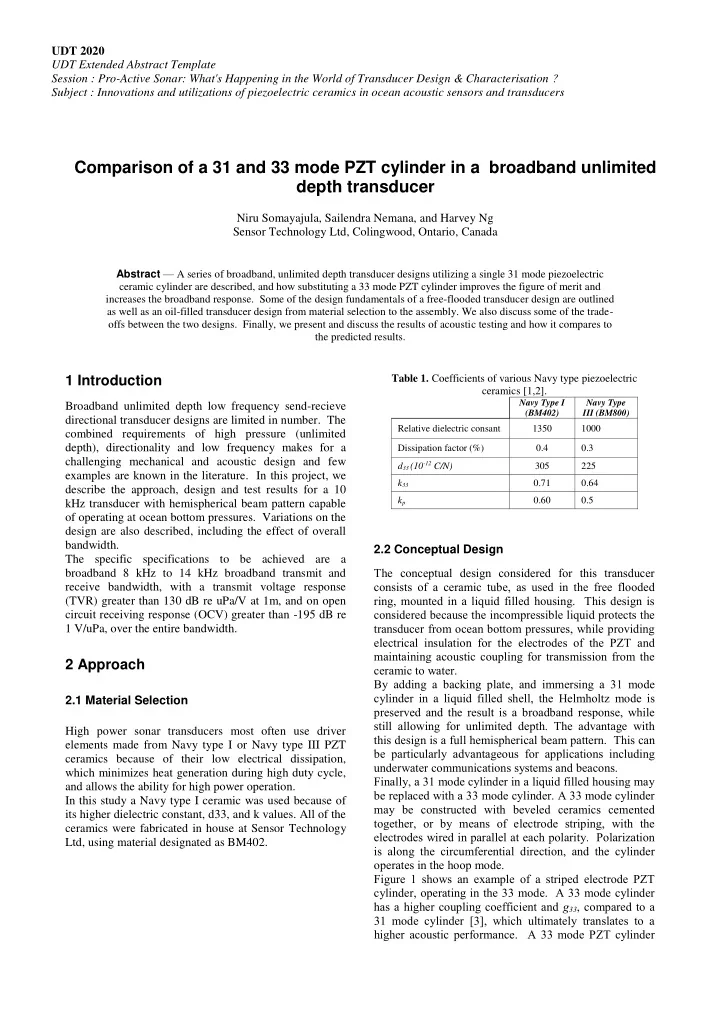
Table 1. Coefficients of various Navy type piezoelectric ceramics [1,2].

Navy Type I (BM402) Navy Type III (BM800) Relative dielectric consant 1350 1000 Dissipation factor (%) 0.4 0.3 d33 (10-12 C/N) 305 225 k33 0.71 0.64 kp 0.60 0.5

2.2 Conceptual Design The conceptual design considered for this transducer consists of a ceramic tube, as used in the free flooded ring, mounted in a liquid filled housing. This design is considered because the incompressible liquid protects the transducer from ocean bottom pressures, while providing electrical insulation for the electrodes of the PZT and maintaining acoustic coupling for transmission from the ceramic to water. By adding a backing plate, and immersing a 31 mode cylinder in a liquid filled shell, the Helmholtz mode is preserved and the result is a broadband response, while still allowing for unlimited depth. The advantage with this design is a full hemispherical beam pattern. This can be particularly advantageous for applications including underwater communications systems and beacons. Finally, a 31 mode cylinder in a liquid filled housing may be replaced with a 33 mode cylinder. A 33 mode cylinder may be constructed with beveled ceramics cemented together, or by means of electrode striping, with the electrodes wired in parallel at each polarity. Polarization is along the circumferential direction, and the cylinder

  • perates in the hoop mode.

Figure 1 shows an example of a striped electrode PZT cylinder, operating in the 33 mode. A 33 mode cylinder has a higher coupling coefficient and g33, compared to a 31 mode cylinder [3], which ultimately translates to a higher acoustic performance. A 33 mode PZT cylinder

slide-2
SLIDE 2

UDT 2020 UDT Extended Abstract Template Session : Pro-Active Sonar: What's Happening in the World of Transducer Design & Characterisation ? Subject : Innovations and utilizations of piezoelectric ceramics in ocean acoustic sensors and transducers can be manufactured by segmenting the cylinder and parallel wiring the striped electrodes.

  • Fig. 1 A Striped electrode PZT tube, operating in the 33 mode

2.3 FEM Modelling A simple model of the liquid filled transducer was performed using COMSOL. The model used a Navy Type I PZT ceramic cylinder, within an oil-filled neoprene shell and a stainless steel end plate. The neoprene was the acoustic transmitting face coupled a spherical body of water with a perfectly matched outer edge layer. Some transducer details were omitted for the sake of decreasing the complexity of modelling. The solved 3-D model for pressure with the stainless steel end cap is shown in Figure 2

  • Fig. 2 3-D model geometry.

2.4 Assembly of Transducers Three transducer designs were assembled. First, a free- flooded ring transducer was chosen as the reference test

  • transducer. Second, a PZT ceramic cylinder of the same

material and geometry was assembled into an oil-filled transducer as our test transducer. The PZT cylinder was centred and affixed into a neoprene boot. The electrodes were connected onto wire, and passed through a stainless steel endplate, which was secured onto the neoprene boot. The assembly was then flooded with oil, with all air ejected from the neoprene boot. Finally, another oil- filled test transducer was constructed with a 33 mode PZT cylinder, of the same material and geometry.

3 Results and Discussion

The three transducers were tested at the Acoustic Open Tank Facility at the Navy Undersea Warfare Center (NUWC) at Newport, NI. The tests for each transducer included Free Field Voltage Sensitivity (FFVS), Transmit Voltage Response (TVR), and beam pattern testing in the both the XY radial plane and the XZ axial plane. Figure 3 shows a comparison of FFVS between the three

  • transducers. We note that the each of the transducers

show a peak sensitivity at the Helmholtz resonance, between 8-9 kHz. The oil filled transducer with a 33 mode cylinder also shows a 6 dB higher sensitivity than the comparable oil filled transducer with a 31 mode cylinder, with a flatter broadband response between 9 kHz-13 kHz.

  • Fig. 3 Free field voltage sensitivity (FFVS) response of the

three transducers from 5 kHz to 20 kHz

Figure 4 shows a comparison of TVR between the three

  • transducers. All three transducers are within 4 dB of each
  • ther, and follow roughly the same curve throughout the

usable bandwidth. We note that although the oil filled 31-mode cylinder transducer has higher peaks at the 9 kHz Helmholtz resonance as well as the fundamental 13 kHz radial resonance, the oil filled 33 mode cylinder transducer has an overall flatter response, which may be desirable for equalizing broadband transmission, without any electronics tuning required, in a communications application.

slide-3
SLIDE 3

UDT 2020 UDT Extended Abstract Template Session : Pro-Active Sonar: What's Happening in the World of Transducer Design & Characterisation ? Subject : Innovations and utilizations of piezoelectric ceramics in ocean acoustic sensors and transducers

  • Fig. 4 Transmit voltage response (TVR) of the three transducers

from 5 kHz to 20 kHz

4 Future Work

The successful design, fabrication and testing of the three transducers revealed opportunities for future work aimed at improving performance. In particular, the oil filled transducer with the 31 mode cylinder may be further tuned, such that thein the aspect ratio of the PZT ceramic may be adjusted to couple the 8 kHz Helmholtz resonance further with the 13 kHz radial resonance. This would improve the transducer by flattening the TVR response over the 8 kHz-13 kHz bandwidth. In addition, this type of oil-filled transducers can be scaled for different frequencies, including lower frequencies, by adjusting the geometry of the PZT ceramic. The two oil-filled transducers are currently undergoing sea trials in an underwater communications system. The transducers being used in a real-world system will be the true test on the effectiveness and longevity of the transducers.

Acknowledgements

Sensor Technology Canada gratefully acknowledges Jon Jon Helgeland of Bifrost Engineering for his work with the transducer FEM work. All acoustic test data was provided by NUWC’s Acoustic Open Tank Facility, an ISO 17025 accredited acoustics calibration lab in the United States.

References

[1] IEEE Standard on Piezoelectricity, ANSI/IEEE Std

176-1987, 1987

[2] MIL-STD-1376B(SH), 24 February 1995 [3] Charles H. Sherman and John L. Butler, Transducers

and Arrays for Underwater Sound, 3rd ed., vol. 2. Springer Science+Business Media, 2007, pp. 91–95.

[4] Junger, Miguel, “Design Parameters of Free-

Flooding Cylindrical Transducers,” Technical Report U-309-210 prepared for Office of Naval Reaserch Acoustic Programs. Cambridge Acoustics Associates, Inc. Cambridge, Massachusetts.

Author/Speaker Biographies

  • Ms. Niru Somayajula is the President & CEO of Sensor

Technology Ltd, a world leader in high-tech manufacturer of underwater sonar solutions employing

  • ver 35 people in Collingwood, Ontario, Canada and in

Dartmouth, Nova Scotia, Canada.