Closure Presentation www.encompass-am.eu The ENCOMPASS project - - PowerPoint PPT Presentation

closure
SMART_READER_LITE
LIVE PREVIEW

Closure Presentation www.encompass-am.eu The ENCOMPASS project - - PowerPoint PPT Presentation

Closure Presentation www.encompass-am.eu The ENCOMPASS project has received funding by the photonics and Factories of the Future (FoF) Public Private Partnerships (PPP), under grant agreement no. H2020-fof- 1 2016-723833-ENCOMPASS. The


slide-1
SLIDE 1

Closure Presentation

The ENCOMPASS project has received funding by the photonics and Factories of the Future (FoF) Public Private Partnerships (PPP), under grant agreement no. H2020-fof- 2016-723833-ENCOMPASS. The project is an initiative of the Photonics and Factories of the Future Public Private Partnership.

1

www.encompass-am.eu

slide-2
SLIDE 2

The ENCOMPASS project has received funding by the photonics and Factories of the Future (FoF) Public Private Partnerships (PPP), under grant agreement no. H2020-fof-2016-723833-ENCOMPASS. The project is an initiative of the Photonics and Factories of the Future Public Private Partnership. 2

CONSORTIUM

slide-3
SLIDE 3

The ENCOMPASS project has received funding by the photonics and Factories of the Future (FoF) Public Private Partnerships (PPP), under grant agreement no. H2020-fof-2016-723833-ENCOMPASS. The project is an initiative of the Photonics and Factories of the Future Public Private Partnership. 3

ENCOMPASS CALL

slide-4
SLIDE 4

The ENCOMPASS project has received funding by the photonics and Factories of the Future (FoF) Public Private Partnerships (PPP), under grant agreement no. H2020-fof-2016-723833-ENCOMPASS. The project is an initiative of the Photonics and Factories of the Future Public Private Partnership. 4

PROJECT MOTIVATION

Manufacturing AM market

─ 3 trillion € (21%) of the EU’s GDP ─ 20% of EU’s employment ⇒ 30 million jobs in 230 000 enterprises (SME mostly) (Eurostat, 2016) ─ EU market share of laser based manufacturing declined (39% in 2008 → 33% in 2012) ⇒ due to competition from Asia (Helmrath, 2015) ─ Threatened by lower wage economies and high tech rivals ─ Grew at a GAGR ≈ 35% to 35 bn € ⇒ will grow to over 90 bn € by 2020 if key technological challenges can be overcome (Wohlers Report 2015) ─ Industrial machinery and consumer goods account for > 36% of the industries using (AM Valles, 2014) ─ Automotive, Aerospace and Medical: focus end- users for ENCOMPASS – 43% of the industries using AM

slide-5
SLIDE 5

The ENCOMPASS project has received funding by the photonics and Factories of the Future (FoF) Public Private Partnerships (PPP), under grant agreement no. H2020-fof-2016-723833-ENCOMPASS. The project is an initiative of the Photonics and Factories of the Future Public Private Partnership.

5

OVERALL OBJECTIVES

Develop an Integrated Design Decision Support (IDDS) system

The integration at digital level enables numerous synergies between the steps in the process chain and the steps themselves (design, build and post-build processes) to be optimised Allow Europe to achieve global leadership in this important field of net-shape AM

slide-6
SLIDE 6

The ENCOMPASS project has received funding by the photonics and Factories of the Future (FoF) Public Private Partnerships (PPP), under grant agreement no. H2020-fof-2016-723833-ENCOMPASS. The project is an initiative of the Photonics and Factories of the Future Public Private Partnership. 6

CHALLENGES OF MULTI STEPPED PROCESS

Component Design PBF-LB build Post-build processing

COMPONENT RELEASE

Expert knowledge and design guidelines Expert selection of scanning strategy and process parameters Expert selected mechanical post- processing and inspection

slide-7
SLIDE 7

The ENCOMPASS project has received funding by the photonics and Factories of the Future (FoF) Public Private Partnerships (PPP), under grant agreement no. H2020-fof-2016-723833-ENCOMPASS. The project is an initiative of the Photonics and Factories of the Future Public Private Partnership. 7

ENCOMPASS FOCAL POINTS

A user support interface within the

CAD environment

Apply monitoring solutions for key variables of the post- PBF-LB processes Digital tools for

simulating and

  • ptimising melt

strategies

Develop a framework for optimisation of

PBF-LB product and

process design Digital tools for simulating post-build material and quality processes Demonstrate benefit of

IDDS for end user

driven case studies across the aerospace, medical and automotive sectors.

slide-8
SLIDE 8

The ENCOMPASS project has received funding by the photonics and Factories of the Future (FoF) Public Private Partnerships (PPP), under grant agreement no. H2020-fof-2016-723833-ENCOMPASS. The project is an initiative of the Photonics and Factories of the Future Public Private Partnership. 8

THE CONCEPT …

✓ Geometry-specific scanning strategies ✓ Targeted feature tracking ✓ Design for manufacture

LPBF Building Post-building processes Design Process

Integrated Design Decision Support (IDDS) system

✓ In-process monitoring ✓ In-process response ✓ Informing downstream ✓ Design for post- processing ✓ Design for inspection ✓ Targeted feature post-processing/inspection

slide-9
SLIDE 9

The ENCOMPASS project has received funding by the photonics and Factories of the Future (FoF) Public Private Partnerships (PPP), under grant agreement no. H2020-fof-2016-723833-ENCOMPASS. The project is an initiative of the Photonics and Factories of the Future Public Private Partnership. 9

IDDS SYSTEM

slide-10
SLIDE 10

10

DESIGN INTERROGATION TOOL (DIT)

The ENCOMPASS project has received funding by the photonics and Factories of the Future (FoF) Public Private Partnerships (PPP), under grant agreement no. H2020-fof-2016-723833-ENCOMPASS. The project is an initiative of the Photonics and Factories of the Future Public Private Partnership.

slide-11
SLIDE 11

The ENCOMPASS project has received funding by the photonics and Factories of the Future (FoF) Public Private Partnerships (PPP), under grant agreement no. H2020-fof-2016-723833-ENCOMPASS. The project is an initiative of the Photonics and Factories of the Future Public Private Partnership. 11

DESIGN INTERROGATION TOOL (DIT)

CAD types:

slide-12
SLIDE 12

WHAT WHY

The ENCOMPASS project has received funding by the photonics and Factories of the Future (FoF) Public Private Partnerships (PPP), under grant agreement no. H2020-fof-2016-723833-ENCOMPASS. The project is an initiative of the Photonics and Factories of the Future Public Private Partnership. 12

ORIENTATION

Ove Overh rhan angs are important to identify as they represent regions where heat cannot be easily dissipated and therefore supports are required to remove excess heat and to prevent distortion

  • f the printed layers.

✓ The orientation tool calculates the angle of each geometry facet relative to the build direction. ✓ Angles are presented as a contour to easily show

  • verhanging regions.

✓ The build direction is always assumed to be the positive Z axis.

slide-13
SLIDE 13

WHAT WHY

The ENCOMPASS project has received funding by the photonics and Factories of the Future (FoF) Public Private Partnerships (PPP), under grant agreement no. H2020-fof-2016-723833-ENCOMPASS. The project is an initiative of the Photonics and Factories of the Future Public Private Partnership. 13

ORIENTATION – LOCAL MINIMA

✓ Having local minima will result in material being printed without any underlying support or any support from adjoining part geometry, this leads to various build issues. ✓ Local minima are downward facing edges of the part geometry that require support but will not be supported by default as the adjacent faces are not classed as

  • verhanging surfaces.
slide-14
SLIDE 14

WHAT WHY

The ENCOMPASS project has received funding by the photonics and Factories of the Future (FoF) Public Private Partnerships (PPP), under grant agreement no. H2020-fof-2016-723833-ENCOMPASS. The project is an initiative of the Photonics and Factories of the Future Public Private Partnership. 14

ORIENTATION – RECOATER EXPOSURE

Facets of the geometry that exhibit the above characteristics can lead to build issues where the wiper may get caught on the feature due to distortion. ✓ Shows facets exposed to the wiper direction (-Y axis) that also have a normal pointing in the negative Z direction.

slide-15
SLIDE 15

WHAT WHY

The ENCOMPASS project has received funding by the photonics and Factories of the Future (FoF) Public Private Partnerships (PPP), under grant agreement no. H2020-fof-2016-723833-ENCOMPASS. The project is an initiative of the Photonics and Factories of the Future Public Private Partnership. 15

OPTIMISE ORIENTATION

Orienting the part to minimise overhangs reduces the need for supports, which has time and cost benefits in build and post-

  • processing. Minimising is difficult to perform manually, hence

having an automated tool to achieve this. ✓ This tool will run a user defined amount of rotations to check for an optimal orientation for the part. This will return the part at the orientation with the lowest Total Overhanging Area. ✓ When complete the optimal orientation will be shown on screen.

slide-16
SLIDE 16

WHAT WHY

The ENCOMPASS project has received funding by the photonics and Factories of the Future (FoF) Public Private Partnerships (PPP), under grant agreement no. H2020-fof-2016-723833-ENCOMPASS. The project is an initiative of the Photonics and Factories of the Future Public Private Partnership. 16

THIN WALLS & SMALL GAPS

✓ Thin walls can be problematic in build as they may lead to

  • distortion. Thin (small) gaps can result in that gap being

unintentionally fused together during build, which may compromise intended part performance. ✓ This evaluation identifies regions of the part geometry that represent thin walls or small gaps that are thinner than a specified limit.

slide-17
SLIDE 17

WHAT WHY

The ENCOMPASS project has received funding by the photonics and Factories of the Future (FoF) Public Private Partnerships (PPP), under grant agreement no. H2020-fof-2016-723833-ENCOMPASS. The project is an initiative of the Photonics and Factories of the Future Public Private Partnership. 17

SURFACE ROUGHNESS

✓ Part specifications typically dictate surface finishes that must be achieved on the finished part. This evaluation allows the user to estimate if any of these surface finish requirements will be violated and if surface finishing will be required.

✓ The surface roughness (SR) tool calculates the angle of each facet relative to the positive and negative build direction. ✓ These angles are then compared to a look-up table that relates angle to predicted surface roughness. ✓ These roughness values are then contoured on the part.

slide-18
SLIDE 18

WHAT WHY

The ENCOMPASS project has received funding by the photonics and Factories of the Future (FoF) Public Private Partnerships (PPP), under grant agreement no. H2020-fof-2016-723833-ENCOMPASS. The project is an initiative of the Photonics and Factories of the Future Public Private Partnership. 18

VOIDS

✓ Detects fully enclosed volumes within the geometry and highlights these to the user ✓ Fully enclosed volumes (voids) in the geometry will result in powder being trapped and are therefore undesirable.

slide-19
SLIDE 19

WHAT WHY

The ENCOMPASS project has received funding by the photonics and Factories of the Future (FoF) Public Private Partnerships (PPP), under grant agreement no. H2020-fof-2016-723833-ENCOMPASS. The project is an initiative of the Photonics and Factories of the Future Public Private Partnership. 19

VOXEL EXPORT

✓ Exports a Voxel mesh of the component. ✓ This is stored locally for use by external DIT tools. ✓ A voxel mesh representation of the part geometry is necessary to perform certain evaluations.

slide-20
SLIDE 20

WHAT WHY

The ENCOMPASS project has received funding by the photonics and Factories of the Future (FoF) Public Private Partnerships (PPP), under grant agreement no. H2020-fof-2016-723833-ENCOMPASS. The project is an initiative of the Photonics and Factories of the Future Public Private Partnership. 20

SLICING

✓ Slices the part into layers. Slice size is defined in the setup

  • stage. Allows for further evaluations to be carried out which

work on the slice geometry.

✓ Slicing the geometry converts that geometry into a format that matches what will be seen by the build process. ✓ This enables slice based geometrical evaluations to be performed.

slide-21
SLIDE 21

WHAT WHY

The ENCOMPASS project has received funding by the photonics and Factories of the Future (FoF) Public Private Partnerships (PPP), under grant agreement no. H2020-fof-2016-723833-ENCOMPASS. The project is an initiative of the Photonics and Factories of the Future Public Private Partnership. 21

TRANSITIONS

✓ Transitions highlights regions of slices which exceed an area ratio from one layer to the next. If the ratio of one layer to the next is exceeded it is highlighted to the user. The ratio is set by the IDDS. ✓ Rapid transitions from slender to bulky geometry can cause heat dissipation issues leading to high stresses, distortion and potential build failure. It is therefore import to highlight these regions so they can be accounted for.

slide-22
SLIDE 22

WHAT WHY

The ENCOMPASS project has received funding by the photonics and Factories of the Future (FoF) Public Private Partnerships (PPP), under grant agreement no. H2020-fof-2016-723833-ENCOMPASS. The project is an initiative of the Photonics and Factories of the Future Public Private Partnership. 22

ELLIPSES

✓ The ellipse evaluation finds ellipses in the model on each

  • slice. These are then highlighted to the user.

✓ Having ellipses in the slice geometry allows specific scan strategies to be applied to those ellipses, resulting in a better quality build.

slide-23
SLIDE 23

WHAT WHY

The ENCOMPASS project has received funding by the photonics and Factories of the Future (FoF) Public Private Partnerships (PPP), under grant agreement no. H2020-fof-2016-723833-ENCOMPASS. The project is an initiative of the Photonics and Factories of the Future Public Private Partnership. 23

CIRCLES

✓ The circle evaluation finds circles in the model on each slice. These are then highlighted to the user. ✓ Having circles in the slice geometry allows specific scan strategies to be applied to those circles, resulting in a better quality build.

slide-24
SLIDE 24

WHAT WHY

The ENCOMPASS project has received funding by the photonics and Factories of the Future (FoF) Public Private Partnerships (PPP), under grant agreement no. H2020-fof-2016-723833-ENCOMPASS. The project is an initiative of the Photonics and Factories of the Future Public Private Partnership. 24

SMALL HOLES

✓ Will locate any holes defined as too small by the IDDS system. ✓ Scans each slice and locates holes in the geometry. ✓ Any hole below the requirements will be highlighted to the user.

✓ Small holes may not build properly due to them being too small relative to the laser beam geometry, powder size and melt characteristics of the material.

slide-25
SLIDE 25

WHAT WHY

The ENCOMPASS project has received funding by the photonics and Factories of the Future (FoF) Public Private Partnerships (PPP), under grant agreement no. H2020-fof-2016-723833-ENCOMPASS. The project is an initiative of the Photonics and Factories of the Future Public Private Partnership. 25

LARGE AREAS

✓ Calculates the area of each surface within each slice. Saves the calculated areas, normalises the data and presents as a contour. Used to demonstrate concentrations of larger areas in the part.

✓ Relatively large slice areas will mean longer laser exposure times to build that slice, which means relatively greater heat input into the part at that slice. ✓ Such an evaluation can therefore be used as a quick way to identify on which slice heat related distortion issues may occur.

slide-26
SLIDE 26

WHAT WHY

The ENCOMPASS project has received funding by the photonics and Factories of the Future (FoF) Public Private Partnerships (PPP), under grant agreement no. H2020-fof-2016-723833-ENCOMPASS. The project is an initiative of the Photonics and Factories of the Future Public Private Partnership. 26

BLOCKED PATHS

✓ The boundary lines of each slice are evaluated against a circle representative of the laser diameter. Where the circle will not fit reveals blocked paths that cannot be built. ✓ These blocked paths indicate thin walls, small areas and sharp corners. ✓ For parts where geometrical accuracy and very fine features are import, this evaluation identifies regions that will not build correctly due to blocked paths.

slide-27
SLIDE 27

The ENCOMPASS project has received funding by the photonics and Factories of the Future (FoF) Public Private Partnerships (PPP), under grant agreement no. H2020-fof-2016-723833-ENCOMPASS. The project is an initiative of the Photonics and Factories of the Future Public Private Partnership. 27

POST PROCESS

Inspection Simulation

– Evaluate line of sight – Detectability of defects – Equipment capabilities

Post-process Simulation

Surface roughness requirements and equipment capabilities Heat treatment cycle for distortions

slide-28
SLIDE 28

28

ENCOMPASS CASE STUDIES

The ENCOMPASS project has received funding by the photonics and Factories of the Future (FoF) Public Private Partnerships (PPP), under grant agreement no. H2020-fof-2016-723833-ENCOMPASS. The project is an initiative of the Photonics and Factories of the Future Public Private Partnership.

slide-29
SLIDE 29

The ENCOMPASS project has received funding by the photonics and Factories of the Future (FoF) Public Private Partnerships (PPP), under grant agreement no. H2020-fof-2016-723833-ENCOMPASS. The project is an initiative of the Photonics and Factories of the Future Public Private Partnership. 29

AEROSPACE CASING

EVALUATION RESULT OBSERVATIONS

Su Surfa face Rough ghne ness Actions stated Build surface roughness would not comply with drawing requirements. Si Simula latio tion Actions stated Simulation shows some distortions in some areas due to transitions. Transit ransitio ions Actions stated Major transitions observed in several areas. Orientation was correct as supports are required to avoid distortion. Lar Large e ar areas eas Actions stated Largest area was identified. A vast transition is observed close to it.

slide-30
SLIDE 30

The ENCOMPASS project has received funding by the photonics and Factories of the Future (FoF) Public Private Partnerships (PPP), under grant agreement no. H2020-fof-2016-723833-ENCOMPASS. The project is an initiative of the Photonics and Factories of the Future Public Private Partnership. 30

AEROSPACE CASING – REDISIGN?

REF. EVALUATION STAGE GEOMETRY FEATURE ACTION DESCRIPTION REDESIGN?

1 Surfa Surface Rou Roughness General Pos Post-Proces essing: Polishing or blasting process required to improve surface roughness. N/A 2 Tra ransitions/ Over erhan angs Top & bottom flange holes Design: Modify angle of internal faces to machine of holes at top and bottom flanges. Yes 3 Tra ransitions/ Over erhan angs Top & bottom flange holes Design: Adapt the transitions of the holes surrounding material avoiding

  • verhanging areas

Yes 4 Tra ransitions Bottom flange Design: Keep current orientation due to major distortion. Supports should be rigid enough. N/A 5 Tra ransitions/ Lar arge e Ar Area eas Bottom flange to casing Design: Avoid introducing much material in transition from bottom flange to casing Yes 6 Tra ransitions/ Over erhan angs Struts bottom area Design: Add material to avoid

  • verhanging area, and smoother

transition. Yes

REF. EVALUATION STAGE GEOMETRY FEATURE ACTION DESCRIPTION REDESIGN?

7 Tra ransitions/ Si Simulation Casing and struts area Design: Section area should be decreased but keeping smoother transitions. Yes 8 Tra ransitions/ Si Simulation Casing and struts area Design: Select with AM expert the appropriate wall thickness able to manufacture. Yes 9 Tra ransitions/ Si Simulation Casing and struts area Design: Adapt circular extrusions between struts and casing. Yes 10 10 Tra ransitions/ Over erhan angs Internal casing area Design: Adapt circular holes at internal casing area to an auto-support shape if possible Yes 11 11 Tra ransitions/ Over erhan angs Struts internal chamber Design: Modify top area of the strut chamber to an auto-support shape. Yes 12 12 Tra ransitions Struts top hole Design: Adapt struts top holes to new casing section design keeping smoothness. Yes 13 13 Tra ransition/ Over erhan angs Casing – top flange external transition Design: Apply smoother transition. Yes

slide-31
SLIDE 31

The ENCOMPASS project has received funding by the photonics and Factories of the Future (FoF) Public Private Partnerships (PPP), under grant agreement no. H2020-fof-2016-723833-ENCOMPASS. The project is an initiative of the Photonics and Factories of the Future Public Private Partnership. 31

AEROSPACE CASING – THE RESULTS

Initial design Optimised Design after IDDS iteration Optimised Part manufactured

slide-32
SLIDE 32

The ENCOMPASS project has received funding by the photonics and Factories of the Future (FoF) Public Private Partnerships (PPP), under grant agreement no. H2020-fof-2016-723833-ENCOMPASS. The project is an initiative of the Photonics and Factories of the Future Public Private Partnership. 32

AEROSPACE BRACKET

EVALUATION RESULT OBSERVATIONS

Ori Orienta tatio tion Actions stated Orientation of the part is not the best position. 3 results were obtained. Su Surfa face Rough ghne ness Actions stated Build surface roughness would not comply with drawing requirements. Bl Blocked d Path ath Actions stated Was detected that the laser cannot reach some areas of the part. Transit ransitio ions Actions stated Major transitions observed in several areas. Orientation was correct as supports are required to avoid distortion.

slide-33
SLIDE 33

The ENCOMPASS project has received funding by the photonics and Factories of the Future (FoF) Public Private Partnerships (PPP), under grant agreement no. H2020-fof-2016-723833-ENCOMPASS. The project is an initiative of the Photonics and Factories of the Future Public Private Partnership. 33

AEROSPACE BRACKET

EVALUATION RESULT OBSERVATIONS

Circ rcle les & & El Ellip ipses Actions stated The contour scanning strategy could be applied, as in its current form in cannot be applied to partial curves. Lar Large e Ar Areas eas Actions stated Some areas of the component are likely to retain heat through the build process as a result of longer exposure to the energy source. Radio adiogra raphic ic Actions stated Radiographic shows areas not acceptable based upon the stress fields. Su Support t Gene nera ratio ion Actions stated Supports were deemed too high, there fore fine supports were used.

slide-34
SLIDE 34

The ENCOMPASS project has received funding by the photonics and Factories of the Future (FoF) Public Private Partnerships (PPP), under grant agreement no. H2020-fof-2016-723833-ENCOMPASS. The project is an initiative of the Photonics and Factories of the Future Public Private Partnership. 34

AEROSPACE BRACKET

REF. EVALUATION STAGE GEOMETRY FEATURE ACTION DESCRIPTION REDESIGN?

1 Orientation General Re-optimize component with 45°

  • verhanging angle constraint

Yes 2 Surface Roughness General Assess resulting surface roughness for suitability Identify where machining will be required Add stock as required Yes 3 Blocked Path Highlighted Regions Review regions and determine if acceptable without re-design No 4 Transitions Bolting Points Remove bolt holes from the build model Yes

REF. EVALUATION STAGE GEOMETRY FEATURE ACTION DESCRIPTION REDESIGN?

5 Circles & Ellipses Highlighted Regions Review highlighted regions and determine whether special parameters to be applied No 6 Large Areas General Review the criteria in the IDDS, perform evidence gathering exercise. Remove the bolt holes in the part to remove the bridging and smooth transitions. Yes 7 Radiographic Highlighted Regions Determine if identified invisible regions acceptable at lower power No 8 Support Generation General Review generated support structure and determine cost effectiveness Yes

slide-35
SLIDE 35

The ENCOMPASS project has received funding by the photonics and Factories of the Future (FoF) Public Private Partnerships (PPP), under grant agreement no. H2020-fof-2016-723833-ENCOMPASS. The project is an initiative of the Photonics and Factories of the Future Public Private Partnership. 35

AEROSPACE CASING – THE RESULTS

Initial design Initial Design Iteration Optimised Design after IDDS iteration

slide-36
SLIDE 36

The ENCOMPASS project has received funding by the photonics and Factories of the Future (FoF) Public Private Partnerships (PPP), under grant agreement no. H2020-fof-2016-723833-ENCOMPASS. The project is an initiative of the Photonics and Factories of the Future Public Private Partnership. 36

SIGMA CRUCIATE SUBSTITUTING (CS) FEMORAL

EVALUATION RESULT OBSERVATIONS

Th Thin n walls lls & & sm small ll gap gaps OK No Thin walls were detected in the evaluation part. Void ids OK No voids were found in the evaluation part. Surf Surface Roug ughness Actions stated Values of surface roughness did not appear realistic. Upon inspection of IDDS system. Only up skin values were inputted into the software. Expected down skin values were not implemented. Li Line ne of si sigh ght OK Some areas of the component cannot be visually inspected, but it is acceptable based on design criteria. Powder OK Software showed areas of trapped powder, however this can be easily cleaned. Ra Radio iogra raphic ic OK Part can be inspected if made from Ti64, however there would be issues with Inconel. Si Simula latio ion Actions stated Not provided as it did not run during test evaluation session.

slide-37
SLIDE 37

The ENCOMPASS project has received funding by the photonics and Factories of the Future (FoF) Public Private Partnerships (PPP), under grant agreement no. H2020-fof-2016-723833-ENCOMPASS. The project is an initiative of the Photonics and Factories of the Future Public Private Partnership. 37

SIGMA CRUCIATE SUBSTITUTING (CS) FEMORAL

EVALUATION RESULT OBSERVATIONS

Bl Blocked Path th OK No blocked path detected. Transit itio ions ns Actions stated Major transitions observed in several areas. Orientation was correct as supports are required to avoid distortion. Circles es OK No relevant circle was identified. El Ellip lipses N/A No ESI license available during test evaluation. Not evaluated Sm Small ll Hole Holes OK No small hole was detected. Lar Large areas Actions stated Largest area was identified. A vast transition is observed close to it.

slide-38
SLIDE 38

REF. EVALUATION STAGE ACTION DESCRIPTION REDESIGN?

1 Surface Roughness Post-Processing: Polishing or blasting process required to improve surface roughness. Yes 2 Orientation Target surface roughness not achievable with AM technology. Post-process step required, and optimal addition of support is required No 3 Trapped powder Ensure there are no regions where powder can be trapped in the component Yes

The ENCOMPASS project has received funding by the photonics and Factories of the Future (FoF) Public Private Partnerships (PPP), under grant agreement no. H2020-fof-2016-723833-ENCOMPASS. The project is an initiative of the Photonics and Factories of the Future Public Private Partnership. 38

SIGMA CRUCIATE SUBSTITUTING (CS) FEMORAL

A: smooth surface for joint mechanism B: surface in contact with bone

slide-39
SLIDE 39

The ENCOMPASS project has received funding by the photonics and Factories of the Future (FoF) Public Private Partnerships (PPP), under grant agreement no. H2020-fof-2016-723833-ENCOMPASS. The project is an initiative of the Photonics and Factories of the Future Public Private Partnership. 39

SIGMA CRUCIATE SUBSTITUTING (CS) FEMORAL

Initial design Optimised Design after IDDS iteration Optimised Part manufactured

slide-40
SLIDE 40

The ENCOMPASS project has received funding by the photonics and Factories of the Future (FoF) Public Private Partnerships (PPP), under grant agreement no. H2020-fof-2016-723833-ENCOMPASS. The project is an initiative of the Photonics and Factories of the Future Public Private Partnership. 40

AUTOMOTIVE MANIFOLD

EVALUATION RESULT OBSERVATIONS

Ove Overh rhan ang Actions stated Optimise Rotation -> need to consider volume fitting inside the platform volume (better UI could simplify the job analysis and modification) Su Support Actions stated Keeping into account the component orientation, in

  • rder to remove internal support proper part orientation

has been selected. Circ rcle les Actions started Despite no critical circle was identified, in order to reduce the internal support, the final channel shape has been redesigned to be auto-support.

slide-41
SLIDE 41

The ENCOMPASS project has received funding by the photonics and Factories of the Future (FoF) Public Private Partnerships (PPP), under grant agreement no. H2020-fof-2016-723833-ENCOMPASS. The project is an initiative of the Photonics and Factories of the Future Public Private Partnership. 41
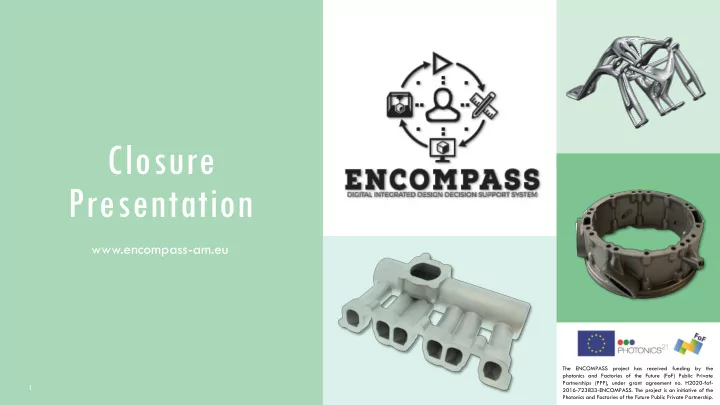
AUTOMOTIVE MANIFOLD

REF. EVALUATION STAGE GEOMETRY FEATURE ACTION DESCRIPTION REDESIGN?

6 Transitions/ Overhangs Struts internal collector Design: Modify top area of the strut collector to an auto-support shape. Yes 7 Transitions/ Large Areas Bottom flange to casing Design: Avoid introducing much material in transition from bottom flange to casing Minimal 8 Transitions/ Overhangs Struts bottom area Design: Add material to avoid

  • verhanging area, and smoother

transition. Minimal 9 Transition /

  • verhangs

Holes Design: hole features could be blanked

  • ff and post drilled

Yes 10 10 Transition /

  • verhangs

Flanges Design: channel flanges seal sets to be blanked off and post machined Yes

REF. EVALUATION STAGE GEOMETRY FEATURE ACTION DESCRIPTION REDESIGN?

1 Surface Roughness General Post-Processing: Polishing or blasting process required to improve surface roughness. N/A 2 Orientation General Design: identify improved

  • rientation in order to minimize

internal support needs Yes 3 Transitions/ Overhangs Channels flange holes Design: Adapt the transitions of the holes surrounding material avoiding overhanging areas Yes 4 Transitions/ Overhangs Internal channels Design: Adapt the internal channels shape in order to avoid internal supports Yes 5 Transitions Bottom flange Design: Keep current orientation due to major distortion. Supports should be rigid enough. N/A

slide-42
SLIDE 42

The ENCOMPASS project has received funding by the photonics and Factories of the Future (FoF) Public Private Partnerships (PPP), under grant agreement no. H2020-fof-2016-723833-ENCOMPASS. The project is an initiative of the Photonics and Factories of the Future Public Private Partnership. 42

AEROSPACE CASING – THE RESULTS

Initial design Optimised Design after IDDS iteration Optimised Part manufactured

slide-43
SLIDE 43

The ENCOMPASS project has received funding by the photonics and Factories of the Future (FoF) Public Private Partnerships (PPP), under grant agreement no. H2020-fof-2016-723833-ENCOMPASS. The project is an initiative of the Photonics and Factories of the Future Public Private Partnership. 43

IMPACT

Manufacturing

✓ Reduce component weight ✓ Reduce production time ✓ Reduce energy usage ✓ Reduce costs of production

Standardization

✓ Contributions to standardization for Personnel Qualification/ Certification using ENCOMPASS Training Programme ✓ Contributions to standardization for PBF-LB (e.g. Design, machines)

Environmental

✓ Reduce of the fuel consumption and emissions ✓ Smoother out gas flows ✓ Reduce noise

Social

✓ Increase economic growth ✓ Create new jobs ✓ Improve adoption of AM ✓ Enable exploitation of AM medical implants

slide-44
SLIDE 44

The ENCOMPASS project has received funding by the photonics and Factories of the Future (FoF) Public Private Partnerships (PPP), under grant agreement no. H2020-fof-2016-723833-ENCOMPASS. The project is an initiative of the Photonics and Factories of the Future Public Private Partnership. 44

THANK YOU!