
SLIDE 1
Closing the Fuel Cycle with Fast Reactors: Indian experience and - - PowerPoint PPT Presentation
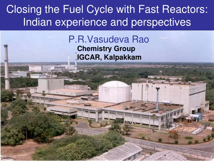
Closing the Fuel Cycle with Fast Reactors: Indian experience and perspectives P.R.Vasudeva Rao Chemistry Group IGCAR, Kalpakkam Energy Scenario for India Nuclear Power Scenario Stage III and Beyond Stage - II Fast Breeder Reactors
Energy sustainability with closing the fuel cycle is the policy; Growth limited by our ability to expand in a robust manner
Stage - II Fast Breeder Reactors
successful operation
achieved in FBTR
pumps operate more than 1,50,000 h
Advanced stage of construction
Nuclear Power Scenario
Stage – III and Beyond Thorium Based Reactors
Evaluation
and enhanced introduction of Thorium Fuel Cycle
development of fusion technology
loop type reactor. The design is same as that of Rapsodie-Fortissimo except for incorporation of SG and TG (agreement signed with CEA, France in 1969).
design and construction
to PFBR with improved economy and enhanced safety by 2020.
the fuel has been carried out in hot cells at various stages of burn-up
GWd/t has been reprocessed in CORAL facility
fuel, which has been loaded in the FBTR core, thus closing the fuel cycle
2011
FBTR is in operation since 1985, It uses a unique U, Pu mixed carbide fuel with high Pu content (Mark I 70 %, Mark II 55 %) The fuel has set an international record in burn-up (165 GWd/t) without any fuel pin failure in the core
Designed by IGCAR and constructed by BHAVINI.
%)
(proposed to be enhanced to 150 GWd/t and subsequently to 200 GWd/t)
Advanced Fuel Fabrication Facility (Tarapur) and subsequent cores in Fast Reactor Fuel Cycle facility (FRFCF) being set up at Kalpakkam, colocated with PFBR
PFBR fuel under irradiation in FBTR has already crossed 100000 MWd/t
RCB Roof Truss construction Sea water outfall channel
Inner vessel GP Roof slab LRP/SRP DHX IHX Horton spheres
a b c d
Main Vessel Erection Dec 2009 Erection of thermal baffles May 2010
458
531
Security FFP - FUTURE EXTENSION 1130
485
610
CPDB CPDB CPDB CPDB CPDB CW Sump 10 Ø600mm Hume pipe (for Drainage) Ø300mm Hume pipe (for water line)590
High mast lighting Height pass test area Parking shed for battery580
10 20
P.F.B.R FRFCF PLANT SITE FRFCF INFRASTRUCTURE
N
TO IGCAR
Commercial Operation by 2012 Operation by 2014 Commercial Operation by 2020
s y
CFBR
Artist’s impression of FRFCF
This facility will be self contained and have all facilities for recycling the fuel from PFBR, including fuel fabrication & assembly plants, reprocessing and waste management facility Layout of FRFCF planned in such a way that future expansion would be possible to meet the requirements of two more 500 MWe FBRs that would be built at Kalpakkam site at later date. Facility will be commissioned in 2014
Inner vessel with single toroidal shell (redan) directly connecting grid plate with the upper cylindrical shell Optimization of vessel thickness on OBE elimination Seismic design based
event Integrated liner and safety vessel with thermal insulation arrangement
Conical shell for reactor assembly support Dome shaped roof slab Welded grid plate with reduced height Eight primary pipes Thick plate Top shield
25% weight reduction
Pi Pin n Irra Irradiatio ion in n FBTR Su Subas assembly Irr Irradiat ation in FBT BTR Ful ull Co Core Meta etallic ic Fuel in FBT BTR
Fle lexible Oxide & Metal tal 50 500 0 MWe Desi sign Metall llic Fue uel l Desi sign 10 1000 00 MWe Uni Units
Dou
time : 30
30 y y for for oxid xide , , 10 10 y y for for meta etal an and d 7 7 ys ys for for impr proved meta etal (w (wit ithout Zr Zr)
Bo Bott ttom Plug ug: Bl Blan anket / ste teel Fuel uel slug ug (U (U-19Pu- 6Zr Zr) So Sodiu dium lev evel l Top Plug ug Plenu m
Na Na bo bonded
Bo Bott ttom Plug ug: Bl Blan anket / ste teel Fuel uel slug ug (U (U-Pu u & & Zr Zr) Top Plug ug Plenu m
Mechanical l bond nded
Zr Zr
Mechanical bonding under development at BARC and sodium bonding at IGCAR
Programmes with breakthrough potential: applications of room temperature ionic liquids as solvents, diluents and electrolysis media, supercritical fluid extraction as waste management tool Collaborations with academic and research institutions towards basic understanding of processes, development of new processes and equipment, and realising innovations with breakthrough potential Human resource development: Advanced courses under the auspices of Homi Bhabha National Institute in fuel cycle related subjects to train and empower young generation for taking up challenging programmes Advanced R & D facilities being planned in XII five year plan period to develop and demonstrate processes such as sol-gel fuel fabrication, partitioning of minor actinide separations and waste form production in engineering scale