
SLIDE 1
Chapter 4
MARIE: An Introduction to a Simple Computer
2
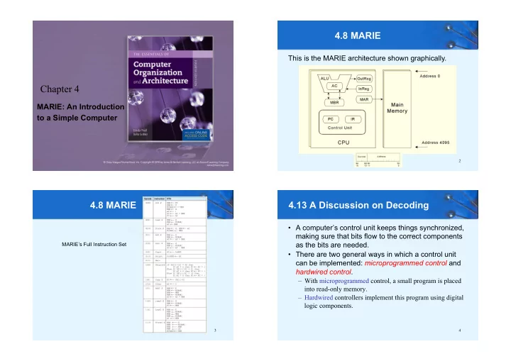
4.8 MARIE
This is the MARIE architecture shown graphically.
MARIE’s Full Instruction Set
4.8 MARIE
3 4
4.13 A Discussion on Decoding
- A computer’s control unit keeps things synchronized,
making sure that bits flow to the correct components as the bits are needed.
- There are two general ways in which a control unit