
SLIDE 1
Network Layer 4-1
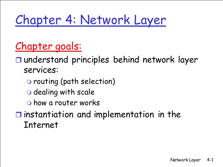
Chapter 4: Network Layer
Chapter goals:
understand principles behind network layer
services:
routing (path selection) dealing with scale how a router works
Chapter 4: Network Layer Chapter goals: understand principles - - PowerPoint PPT Presentation
Chapter 4: Network Layer Chapter goals: understand principles behind network layer services: routing (path selection) dealing with scale how a router works instantiation and implementation in the Internet Network Layer 4-1
Network Layer 4-1
routing (path selection) dealing with scale how a router works
Network Layer 4-2
network data link physical network data link physical network data link physical network data link physical network data link physical network data link physical network data link physical network data link physical application transport network data link physical application transport network data link physical
Network Layer 4-3
Routing algorithms
Network Layer 4-4
1
2 3
0111
value in arriving packet’s header
routing algorithm local forwarding table header value output link
0100 0101 0111 1001 3 2 2 1
4-5
Network Layer
Routing Algorithm
data plane control plane 5-6
Network Layer 1 2 0111
values in arriving packet header
3
data plane control plane
Remote Controller CA
CA CA CA CA 5-7
Network Layer 1 2 0111 3
values in arriving packet header
Network Layer 4-8
ATM, frame relay, X.25
Routers get involved
Network: between two hosts Transport: between two processes
Network Layer 4-9
Service: host-to-host No choice: network provides one or the other Implementation: in the core
Network Layer 4-10
call setup, teardown for each call before data can flow each packet carries VC identifier (not destination host
every router on source-dest path maintains “state” for
link, router resources (bandwidth, buffers) may be
performance-wise network actions along source-to-dest path
Network Layer 4-11
1.
2.
3.
New VC number comes from forwarding table
Network Layer 4-12
12 22 32
1 2 3
VC number interface number Incoming interface Incoming VC # Outgoing interface Outgoing VC # 1 12 3 22 2 63 1 18 3 7 2 17 1 97 3 87 … … … …
Network Layer 4-13
Network Layer 4-14
no network-level concept of “connection”
packets between same source-dest pair may take
Network Layer 4-15
Destination Address Range Link Interface 11001000 00010111 00010000 00000000 through 11001000 00010111 00010111 11111111 11001000 00010111 00011000 00000000 through 1 11001000 00010111 00011000 11111111 11001000 00010111 00011001 00000000 through 2 11001000 00010111 00011111 11111111
3
Network Layer 4-16
Prefix Link Interface 11001000 00010111 00010 11001000 00010111 00011000 1 11001000 00010111 00011 2
3 DA: 11001000 00010111 00011000 10101010 Examples DA: 11001000 00010111 00010110 10100001 Which interface? Which interface?
Network Layer 4-17
data exchange among
“elastic” service, no strict
“smart” end systems
can adapt, perform
simple inside network,
many link types
different characteristics uniform service difficult
evolved from telephony human conversation:
strict timing, reliability
need for guaranteed
“dumb” end systems
telephones complexity inside
Network Layer 4-18
forwarding table
Routing protocols
IP protocol
ICMP protocol
Transport layer: TCP, UDP Link layer physical layer
Network Layer 4-19
ver length 32 bits
16-bit identifier Internet checksum time to live 32 bit source IP address IP protocol version number header length (bytes) max number remaining hops (decremented at each router) for fragmentation/ reassembly total datagram length (bytes) upper layer protocol to deliver payload to head. len type of service “type” of data flgs fragment
upper layer 32 bit destination IP address Options (if any) E.g. timestamp, record route taken, specify list of routers to visit.
20 bytes of TCP 20 bytes of IP = 40 bytes + app
Network Layer 4-20
network links have MTU
(max.transfer size) - largest possible link-level frame.
different link types,
different MTUs
large IP datagram divided
(“fragmented”) within net
one datagram becomes
several datagrams
“reassembled” only at final
destination
IP header bits used to
identify, order related fragments
fragmentation: in: one large datagram
reassembly
Network Layer 4-21
ID =x
=0 fragflag =0 length =4000 ID =x
=0 fragflag =1 length =1500 ID =x
=185 fragflag =1 length =1500 ID =x
=370 fragflag =0 length =1040 One large datagram becomes several smaller datagrams
4000 byte
MTU = 1500 bytes
1480 bytes in data field
1480/8
Network Layer 4-22
router’s typically have
host may have multiple
IP addresses
223.1.1.1 223.1.1.2 223.1.1.3 223.1.1.4 223.1.2.9 223.1.2.2 223.1.2.1 223.1.3.2 223.1.3.1 223.1.3.27 223.1.1.1 = 11011111 00000001 00000001 00000001 223 1 1 1
Network Layer 4-23
subnet part (high
host part (low order
device interfaces with
can physically reach
223.1.1.1 223.1.1.2 223.1.1.3 223.1.1.4 223.1.2.9 223.1.2.2 223.1.2.1 223.1.3.2 223.1.3.1 223.1.3.27
network consisting of 3 subnets LAN
Network Layer 4-24
223.1.1.0/24 223.1.2.0/24 223.1.3.0/24
Network Layer 4-25
223.1.1.1 223.1.1.3 223.1.1.4 223.1.2.2 223.1.2.1 223.1.2.6 223.1.3.2 223.1.3.1 223.1.3.27 223.1.1.2 223.1.7.0 223.1.7.1 223.1.8.0 223.1.8.1 223.1.9.1 223.1.9.2
Network Layer 4-26
subnet portion of address of arbitrary length address format: a.b.c.d/x, where x is # bits in
subnet part host part
Network Layer 4-27
Wintel: control-panel->network->configuration-
UNIX: /etc/rc.config
“plug-and-play”
Network Layer 4-28
ISP's block 11001000 00010111 00010000 00000000 200.23.16.0/20 Organization 0 11001000 00010111 00010000 00000000 200.23.16.0/23 Organization 1 11001000 00010111 00010010 00000000 200.23.18.0/23 Organization 2 11001000 00010111 00010100 00000000 200.23.20.0/23 ... ….. …. …. Organization 7 11001000 00010111 00011110 00000000 200.23.30.0/23
Network Layer 4-29
“Send me anything with addresses beginning 200.23.16.0/20”
200.23.16.0/23 200.23.18.0/23 200.23.30.0/23
Fly-By-Night-ISP Organization 0 Organization 7 Internet Organization 1 ISPs-R-Us “Send me anything with addresses beginning 199.31.0.0/16”
200.23.20.0/23
Organization 2
Hierarchical addressing allows efficient advertisement of routing information:
Network Layer 4-30
ISPs-R-Us has a more specific route to Organization 1
“Send me anything with addresses beginning 200.23.16.0/20”
200.23.16.0/23 200.23.18.0/23 200.23.30.0/23
Fly-By-Night-ISP Organization 0 Organization 7 Internet Organization 1 ISPs-R-Us “Send me anything with addresses beginning 199.31.0.0/16
200.23.20.0/23
Organization 2
Network Layer 4-31
allocates addresses manages DNS assigns domain names, resolves disputes
Network Layer 4-32
10.0.0.1 10.0.0.2 10.0.0.3 10.0.0.4 138.76.29.7
local network (e.g., home network) 10.0.0/24 rest of Internet
Network Layer 4-33
no need to be allocated range of addresses from ISP:
can change addresses of devices in local network
can change ISP without changing addresses of
devices inside local net not explicitly addressable,
Network Layer 4-34
outgoing datagrams: replace (source IP address, port
remember (in NAT translation table) every (source
incoming datagrams: replace (NAT IP address, new
Network Layer 4-35
10.0.0.1 10.0.0.2 10.0.0.3
S: 10.0.0.1, 3345 D: 128.119.40.186, 80
1
10.0.0.4 138.76.29.7
1: host 10.0.0.1 sends datagram to 128.119.40, 80 NAT translation table WAN side addr LAN side addr 138.76.29.7, 5001 10.0.0.1, 3345 …… ……
S: 128.119.40.186, 80 D: 10.0.0.1, 3345
4
S: 138.76.29.7, 5001 D: 128.119.40.186, 80
2 2: NAT router changes datagram source addr from 10.0.0.1, 3345 to 138.76.29.7, 5001, updates table
S: 128.119.40.186, 80 D: 138.76.29.7, 5001
3 3: Reply arrives
138.76.29.7, 5001 4: NAT router changes datagram dest addr from 138.76.29.7, 5001 to 10.0.0.1, 3345
Network Layer 4-36
60,000 simultaneous connections with a single
routers should only process up to layer 3 violates end-to-end argument
address shortage should instead be solved by
Network Layer 4-37
used by hosts & routers to
communicate network-level information
error reporting:
unreachable host, network, port, protocol
echo request/reply (used
by ping)
network-layer “above” IP:
ICMP msgs carried in IP
datagrams
ICMP message: type, code plus
first 8 bytes of IP datagram causing error Type Code description 0 0 echo reply (ping) 3 0 dest. network unreachable 3 1 dest host unreachable 3 2 dest protocol unreachable 3 3 dest port unreachable 3 6 dest network unknown 3 7 dest host unknown 4 0 source quench (congestion control - not used) 8 0 echo request (ping) 9 0 route advertisement 10 0 router discovery 11 0 TTL expired 12 0 bad IP header
Network Layer 4-38
Source sends series of
First has TTL =1 Second has TTL=2, etc. Unlikely port number
When nth datagram arrives
Router discards datagram And sends to source an
ICMP message (type 11, code 0)
Message includes name of
router& IP address
When ICMP message
Traceroute does this 3
UDP segment eventually
Destination returns ICMP
When source gets this
header format helps speed processing/forwarding header changes to facilitate QoS
fixed-length 40 byte header no fragmentation allowed
4-39
Network Layer
data destination address (128 bits) source address (128 bits) payload len next hdr hop limit flow label pri ver 32 bits
4-40
Network Layer
additional message types, e.g. “Packet Too Big” multicast group management functions
4-41
Network Layer
IPv4 source, dest addr IPv4 header fields
IPv4 datagram IPv6 datagram
IPv4 payload UDP/TCP payload IPv6 source dest addr IPv6 header fields 4-42
Network Layer
physical view:
IPv4 IPv4
A B
IPv6 IPv6
E
IPv6 IPv6
F C D logical view:
IPv4 tunnel connecting IPv6 routers
E
IPv6 IPv6
F A B
IPv6 IPv6
4-43
Network Layer
flow: X src: A dest: F data
A-to-B: IPv6
Flow: X Src: A Dest: F data
src:B dest: E
B-to-C: IPv6 inside IPv4 E-to-F: IPv6
flow: X src: A dest: F data
B-to-C: IPv6 inside IPv4
Flow: X Src: A Dest: F data
src:B dest: E physical view: A B
IPv6 IPv6
E
IPv6 IPv6
F C D logical view:
IPv4 tunnel connecting IPv6 routers
E
IPv6 IPv6
F A B
IPv6 IPv6
IPv4 IPv4
4-44
Network Layer
it has been 20 years and counting! think of application-level changes in last 20 years: WWW,
Why?
4-45
Network Layer
Network Layer 4-46
1
2 3
0111
value in arriving packet’s header
routing algorithm local forwarding table header value output link
0100 0101 0111 1001 3 2 2 1
Network Layer 4-47
2 2 1 3 1 1 2 5 3 5 Graph: G = (N,E) N = set of routers = { u, v, w, x, y, z } E = set of links ={ (u,v), (u,x), (v,x), (v,w), (x,w), (x,y), (w,y), (w,z), (y,z) }
Remark: Graph abstraction is useful in other network contexts Example: P2P, where N is set of peers and E is set of TCP connections
Network Layer 4-48
2 2 1 3 1 1 2 5 3 5
inversely related to bandwidth,
congestion Cost of path (x1, x2, x3,…, xp) = c(x1,x2) + c(x2,x3) + … + c(xp-1,xp) Question: What’s the least-cost path between u and z ?
Network Layer 4-49
all routers have complete
“link state” algorithms
router knows physically-
iterative process of
“distance vector” algorithms
periodic update in response to link
Network Layer 4-50
net topology, link costs
accomplished via “link
all nodes have same info
computes least cost paths
gives forwarding table
iterative: after k
Network Layer 4-51
Network Layer 4-52
∞ ∞
2 2 1 3 1 1 2 5 3 5
Network Layer 4-53
1 1+e e e 1 1
2+e 1+e 1
2+e 1+e 1 0 0
2+e e 1+e 1
Network Layer 4-54
Network Layer 4-55
2 2 1 3 1 1 2 5 3 5
Network Layer 4-56
For each neighbor v, x maintains
Network Layer 4-57
Network Layer 4-58
local link cost change DV update message from
each node notifies
neighbors then notify
their neighbors if necessary
Network Layer 4-59
X X X w
Network Layer 4-60
w X X X X X w w
Network Layer 4-61
1 2 7
Network Layer 4-62
1 2 7
D (Y,Z)
X
c(X,Z) + min {D (Y,w)}
w
= = 7+1 = 8
Z
D (Z,Y)
X
c(X,Y) + min {D (Z,w)}
w
= = 2+1 = 3
Y
Network Layer 4-63
node detects local link cost change updates distance table (line 15) if cost change in least cost path,
1 4 50
1
algorithm terminates
Network Layer 4-64
good news travels fast bad news travels slow -
1 4 50
60
algorithm continues
Network Layer 4-65
Z tells Y its (Z’s) distance to X is
will this completely solve count to
1 4 50
60
algorithm terminates
Network Layer 4-66
LS: with n nodes, E links,
DV: exchange between
convergence time varies
LS: O(n2) algorithm requires
may have oscillations
DV: convergence time varies
may be routing loops count-to-infinity problem
node can advertise
each node computes only
DV node can advertise
each node’s table used by
network
Network Layer 4-67
can’t store all dest’s in
routing table exchange
internet = network of
each network admin may
5-68 Network Layer
Network Layer 4-69
AS2
Intra-AS Routing algorithm Inter-AS Routing algorithm
Forwarding table
Intra-AS sets entries
Inter-AS & Intra-As
Network Layer 4-70
AS2
Router should forward
Network Layer 4-71
RIP: Routing Information Protocol OSPF: Open Shortest Path First IGRP: Interior Gateway Routing Protocol (Cisco
Network Layer 4-72
u v w x y z destination hops u 1 v 2 w 2 x 3 y 3 z 2
Network Layer 4-73
Network Layer 4-74
Routing table in D
Network Layer 4-75
Routing table in D
Dest Next hops w
C 4 …. … ...
Network Layer 4-76
routes via neighbor invalidated new advertisements sent to neighbors neighbors in turn send out new advertisements (if
link failure info quickly propagates to entire net poison reverse used to prevent ping-pong loops
Network Layer 4-77
physical link network forwarding (IP) table Transport (UDP) routed physical link network (IP) Transport (UDP) routed forwarding table
Network Layer 4-78
LS packet dissemination Topology map at each node Route computation using Dijkstra’s algorithm
Carried in OSPF messages directly over IP (rather than TCP
Network Layer 4-79
Multicast OSPF (MOSPF) uses same topology data
Network Layer 4-80
Network Layer 4-81
Link-state advertisements only in area each nodes has detailed area topology; only know
“glue that holds the Internet together”
determine “good” routes to other networks based on
5-82 Network Layer
eBGP connectivity iBGP connectivity 1b 1d 1c 1a 2b 2d 2c 2a 3b 3d 3c 3a
5-83 Network Layer
1c ∂ ∂ gateway routers run both eBGP and iBGP protools
AS3 promises to AS2 it will forward datagrams towards X
1b 1d 1c 1a 2b 2d 2c 2a 3b 3d 3c 3a
X
BGP advertisement: AS3, X
5-84 Network Layer
Network Layer 4-85
With eBGP session between 3a and 1c, AS3 sends prefix
1c can then use iBGP do distribute this new prefix reach info
1b can then re-advertise the new reach info to AS2 over the
When router learns about a new prefix, it creates an entry
AS2
eBGP session iBGP session
Network Layer 4-86
prefix + attributes = “route”
AS-PATH: contains the ASs through which the advert
NEXT-HOP: Indicates the specific internal-AS router to
Network Layer 4-87
1.
2.
3.
4.
Network Layer 4-88
OPEN: opens TCP connection to peer and
UPDATE: advertises new path (or withdraws old) KEEPALIVE keeps connection alive in absence of
NOTIFICATION: reports errors in previous msg;
Network Layer 4-89
Figure 4.5-BGPnew: a simple BGP scenario
A B C W X Y
legend: customer network: provider network
X does not want to route from B via X to C .. so X will not advertise to B a route to C
Network Layer 4-90
Figure 4.5-BGPnew: a simple BGP scenario
A B C W X Y
legend: customer network: provider network
No way! B gets no “revenue” for routing CBAW since neither
B wants to force C to route to w via A B wants to route only to/from its customers!
Network Layer 4-91
Network Layer 4-92
Network Layer 4-93
given datagram dest., lookup output port
goal: complete input port processing at
queuing: if datagrams arrive faster than
Network Layer 4-94
Network Layer 4-95
Input Port Output Port Memory System Bus
Network Layer 4-96
Network Layer 4-97
queueing delay and loss due to input buffer overflow!
transferred. lower red packet is blocked
switch fabric
green packet experiences HOL blocking
switch fabric
4-98
Network Layer
line termination link layer protocol (send) switch fabric datagram buffer queueing
4-99 Network Layer
at t, packets more from input to output
later
switch fabric switch fabric
4-100
Network Layer
real-world example? discard policy: if packet arrives to full queue: who to
queue (waiting area) packet arrivals packet departures link (server) 4-101
Network Layer
class may depend on
real world example?
high priority queue (waiting area) low priority queue (waiting area) arrivals classify departures link (server)
1 3 2 4 5 5 5 2 2 1 1 3 3 4 4
arrivals departures packet in service 4-102
Network Layer
1 2 3 4 5 5 5 2 3 1 1 3 3 4 4
arrivals departures packet in service 4-103
Network Layer