
SLIDE 1
CHAPTER 12: PRACTICAL ISSUES
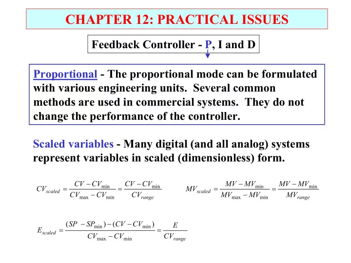
Feedback Controller - P, I and D Proportional - The proportional mode can be formulated with various engineering units. Several common methods are used in commercial systems. They do not change the performance of the controller. Scaled variables - Many digital (and all analog) systems represent variables in scaled (dimensionless) form.
range scaled
CV CV CV CV CV CV CV CV
min min max min
− = − − =
range scaled
CV E CV CV CV CV SP SP E = − − − − =
min max min min
) ( ) (
range scaled
MV MV MV MV MV MV MV MV
min min max min
− = − − =