
SLIDE 1
Introduction 1-1
Introduction 1-1
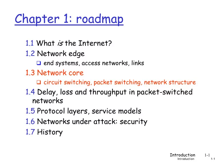
Chapter 1: roadmap
1.1 What is the Internet? 1.2 Network edge
end systems, access networks, links
1.3 Network core
circuit switching, packet switching, network structure
Chapter 1: roadmap 1.1 What is the Internet? 1.2 Network edge end - - PowerPoint PPT Presentation
Chapter 1: roadmap 1.1 What is the Internet? 1.2 Network edge end systems, access networks, links 1.3 Network core circuit switching, packet switching, network structure 1.4 Delay, loss and throughput in packet-switched networks 1.5
Introduction 1-1
Introduction 1-1
end systems, access networks, links
circuit switching, packet switching, network structure
Introduction 1-2
simplest no flexibility "permanent"
Network of intermediate paths j oined by switches PS
PS
Introduction 1-3
Introduction 1-3
mesh of interconnected
the fundamental
circuit switching:
packet-switching: data
Introduction 1-4
Introduction 1-4
link bandwidth, switch
dedicated resources:
circuit-like
call setup required
Introduction 1-5
Introduction 1-5
pieces allocated to calls resource piece idle if
dividing link bandwidth
frequency division time division
Introduction 1-6
Paths traverse links from switch to switch Inter-switch links each carry multiple circuits –
Links transmit a range or band of (analog) signal
Introduction 1-7
Introduction 1-7
Introduction 1-8
A link capable of 100 MHz total bandwidth carries?
see <www.csgnetwork.com/ tvfreqtable.html> How much bandwidth does a tv cable need, to deliver
pringsteen/ 57-Channels-And- Nothin-On.html>
Introduction 1-9
Timeslot duration is sufficient to carry a certain amount
Introduction 1-10
Introduction 1-10
All links are 1.536 Mbps Each link uses TDM with 24 slots/sec 500 msec to establish end-to-end circuit
Introduction 1-11
Introduction 1-11
user A, B packets share
each packet uses full link
resources used as needed
aggregate resource
congestion: packets
store and forward:
Node receives complete
packet before forwarding
Bandwidth division into “pieces” Dedicated allocation Resource reservation
Introduction 1-12
Introduction 1-12
100 Mb/s Ethernet 1.5 Mb/s
statistical multiplexing
queue of packets waiting for output link
Introduction 1-13
Introduction 1-13
takes L/R seconds to
store and forward:
delay = 3L/R (assuming
L = 7.5 Mbits R = 1.5 Mbps transmission delay = 15
R R R L more on delay shortly …
Introduction 1-14
Introduction 1-14
1 Mb/s link each user:
100 kb/s when “active” active 10% of time
circuit-switching:
10 users
packet switching:
with 35 users,
probability > 10 active at same time is less than .0004
Q: how did we get value 0.0004?
Introduction 1-15
Introduction 1-15
great for bursty data
resource sharing simpler, no call setup
excessive congestion: packet delay and loss
protocols needed for reliable data transfer,
Q: How to provide circuit-like behavior?
bandwidth guarantees needed for audio/video apps still an unsolved problem (chapter 7)
Q: human analogies of reserved resources (circuit switching) versus on-demand allocation (packet-switching)?
Introduction 1-16
Introduction 1-16
roughly hierarchical at center: “tier-1” ISPs (e.g., Verizon, Sprint, AT&T,
treat each other as equals
Tier-1 providers interconnect (peer) privately
Introduction 1-17 Introduction 1-17
to/from customers peering to/from backbone
POP: point-of-presence
Introduction 1-18
Introduction 1-18
“Tier-2” ISPs: smaller (often regional) ISPs
Connect to one or more tier-1 ISPs, possibly other tier-2 ISPs
Tier-2 ISP Tier-2 ISP Tier-2 ISP Tier-2 ISP Tier-2 ISP Tier-2 ISP pays tier-1 ISP for connectivity to rest of Internet
tier-2 ISP is
customer of tier-1 provider Tier-2 ISPs also peer privately with each other.
Introduction 1-19
Introduction 1-19
“Tier-3” ISPs and local ISPs
last hop (“access”) network (closest to end systems)
Tier-2 ISP Tier-2 ISP Tier-2 ISP Tier-2 ISP Tier-2 ISP local ISP local ISP local ISP local ISP local ISP Tier 3 ISP local ISP local ISP local ISP Local and tier- 3 ISPs are customers of higher tier ISPs connecting them to rest
Introduction 1-20
Introduction 1-20
a packet passes through many networks!
Tier-2 ISP Tier-2 ISP Tier-2 ISP Tier-2 ISP Tier-2 ISP local ISP local ISP local ISP local ISP local ISP Tier 3 ISP local ISP local ISP local ISP