1
play

1 Public Circuit Switched Network Telecomms Components - PDF document

William Stallings Switching Networks Data and Computer Communications Long distance transmission is typically done 7 th Edition over a network of switched nodes Nodes not concerned with content of data End devices are stations


  1. William Stallings Switching Networks Data and Computer Communications • Long distance transmission is typically done 7 th Edition over a network of switched nodes • Nodes not concerned with content of data • End devices are stations Chapter 10 —Computer, terminal, phone, etc. Circuit Switching and Packet • A collection of nodes and connections is a Switching communications network • Data routed by being switched from node to node Nodes Simple Switched Network • Nodes may connect to other nodes only, or to stations and other nodes • Node to node links usually multiplexed • Network is usually partially connected —Some redundant connections are desirable for reliability • Two different switching technologies —Circuit switching —Packet switching
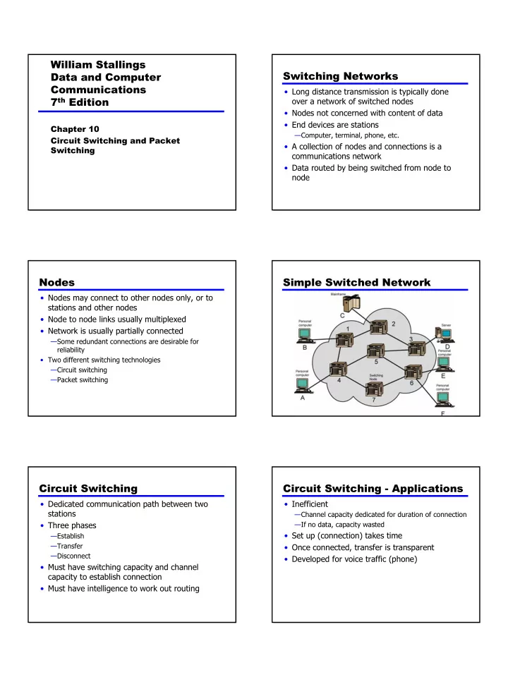
 Circuit Switching Circuit Switching - Applications • Dedicated communication path between two • Inefficient stations —Channel capacity dedicated for duration of connection • Three phases —If no data, capacity wasted • Set up (connection) takes time —Establish —Transfer • Once connected, transfer is transparent —Disconnect • Developed for voice traffic (phone) • Must have switching capacity and channel capacity to establish connection • Must have intelligence to work out routing 1

  2. Public Circuit Switched Network Telecomms Components • Subscriber — Devices attached to network • Subscriber line — Local Loop — Subscriber loop — Connection to network — Few km up to few tens of km • Exchange — Switching centers — End office - supports subscribers • Trunks — Branches between exchanges — Multiplexed Circuit Establishment Circuit Switch Elements Circuit Switching Concepts Blocking or Non-blocking • Digital Switch • Blocking —Provide transparent signal path between devices —A network is unable to connect stations because all • Network Interface paths are in use —A blocking network allows this • Control Unit —Used on voice systems —Establish connections • Generally on demand • Short duration calls • Handle and acknowledge requests • Non-blocking • Determine if destination is free —Permits all stations to connect (in pairs) at once • construct path —Maintain connection —Used for some data connections —Disconnect 2

  3. Space Division Switching Space Division Switch • Developed for analog environment • Separate physical paths • Crossbar switch —Number of crosspoints grows as square of number of stations —Loss of crosspoint prevents connection —Inefficient use of crosspoints • All stations connected, only a few crosspoints in use —Non-blocking Three Stage Space Division Multistage Switch Switch • Reduced number of crosspoints • More than one path through network —Increased reliability • More complex control • May be blocking Time Division Switching Control Signaling Functions • Modern digital systems rely on intelligent control • Audible communication with subscriber of space and time division elements • Transmission of dialed number • Use digital time division techniques to set up • Call can not be completed indication and maintain virtual circuits • Call ended indication • Partition low speed bit stream into pieces that • Signal to ring phone share higher speed stream • Billing info • Equipment and trunk status info • Diagnostic info • Control of specialist equipment 3

  4. Control Signal Sequence Switch to Switch Signaling • Both phones on hook • Subscribers connected to different switches • Subscriber lifts receiver (off hook) • Originating switch seizes interswitch trunk • End office switch signaled • Send off hook signal on trunk, requesting digit • Switch responds with dial tone register at target switch (for address) • Caller dials number • If target not busy, send ringer signal to target • Terminating switch sends off hook followed by subscriber on hook (wink) to show register ready • Feedback to caller • Originating switch sends address — Ringing tone, engaged tone, unobtainable • Target accepts call by lifting receiver • Switch terminates ringing signal and ringing tone • Switch establishes connection • Connection release when Source subscriber hangs up Location of Signaling In Channel Signaling • Subscriber to network • Use same channel for signaling and call — Requires no additional transmission facilities —Depends on subscriber device and switch • Inband • Within network — Uses same frequencies as voice signal —Management of subscriber calls and network — Can go anywhere a voice signal can —ore complex — Impossible to set up a call on a faulty speech path • Out of band — Voice signals do not use full 4kHz bandwidth — Narrow signal band within 4kHz used for control — Can be sent whether or not voice signals are present — Need extra electronics — Slower signal rate (narrow bandwidth) Drawbacks of In Channel Signaling Common Channel Signaling • Limited transfer rate • Control signals carried over paths independent of voice channel • Delay between entering address (dialing) and • One control signal channel can carry signals for a connection number of subscriber channels • Overcome by use of common channel signaling • Common control channel for these subscriber lines • Associated Mode — Common channel closely tracks interswitch trunks • Disassociated Mode — Additional nodes (signal transfer points) — Effectively two separate networks 4

  5. Common v. In Channel Common Signaling Channel Signaling Modes SS7 Signaling System Number 7 Signaling Network Elements • Signaling point (SP) • SS7 —Any point in the network capable of handling SS7 • Common channel signaling scheme control message • ISDN • Signal transfer point (STP) • Optimized for 64k digital channel network —A signaling point capable of routing control messages • Call control, remote control, management and • Control plane maintenance —Responsible for establishing and managing connections • Reliable means of transfer of info in sequence • Information plane • Will operate over analog and below 64k —Once a connection is set up, info is transferred in the • Point to point terrestrial and satellite links information plane Transfer Points Signaling Network Structures • STP capacities —Number of signaling links that can be handled —Message transfer time —Throughput capacity • Network performance —Number of SPs —Signaling delays • Availability and reliability —Ability of network to provide services in the face of STP failures 5

  6. Softswitch Architecture Traditional Circuit Switching • General purpose computer running software to make it a smart phone switch • Lower costs • Greater functionality — Packetizing of digitized voice data — Allowing voice over IP • Most complex part of telephone network switch is software controlling call process — Call routing — Call processing logic — Typically running on proprietary processor • Separate call processing from hardware function of switch • Physical switching done by media gateway • Call processing done by media gateway controller Softswitch Packet Switching Principles • Circuit switching designed for voice —Resources dedicated to a particular call —Much of the time a data connection is idle —Data rate is fixed • Both ends must operate at the same rate Basic Operation Use of Packets • Data transmitted in small packets —Typically 1000 octets —Longer messages split into series of packets —Each packet contains a portion of user data plus some control info • Control info —Routing (addressing) info • Packets are received, stored briefly (buffered) and past on to the next node —Store and forward 6

  7. Advantages Switching Technique • Line efficiency • Station breaks long message into packets — Single node to node link can be shared by many packets over • Packets sent one at a time to the network time • Packets handled in two ways — Packets queued and transmitted as fast as possible • Data rate conversion —Datagram — Each station connects to the local node at its own speed —Virtual circuit — Nodes buffer data if required to equalize rates • Packets are accepted even when network is busy — Delivery may slow down • Priorities can be used Datagram Datagram Diagram • Each packet treated independently • Packets can take any practical route • Packets may arrive out of order • Packets may go missing • Up to receiver to re-order packets and recover from missing packets Virtual Virtual Circuit Circuit Diagram • Preplanned route established before any packets sent • Call request and call accept packets establish connection (handshake) • Each packet contains a virtual circuit identifier instead of destination address • No routing decisions required for each packet • Clear request to drop circuit • Not a dedicated path 7

Download Presentation
Download Policy: The content available on the website is offered to you 'AS IS' for your personal information and use only. It cannot be commercialized, licensed, or distributed on other websites without prior consent from the author. To download a presentation, simply click this link. If you encounter any difficulties during the download process, it's possible that the publisher has removed the file from their server.

Recommend


More recommend