
SLIDE 1
Beamline for Materials Measurement (BMM) Beamline for Materials - - PowerPoint PPT Presentation
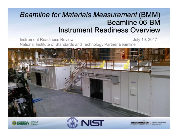
Beamline for Materials Measurement (BMM) Beamline for Materials Measurement (BMM) Beamline 06-BM Beamline 06-BM Instrument Readiness Overview Instrument Readiness Overview Instrument Readiness Review July 19, 2017 National Institute of
Background Pillar1: Documentation Pillar II: Hardware Pillar III: Personnel
Background Pillar1: Documentation Pillar II: Hardware Pillar III: Personnel
Background Pillar1: Documentation Pillar II: Hardware Pillar III: Personnel
Photon Source Three-pole wiggler Operating Energy Range 4500 eV to 23000 eV Monochromator Double crystal monochromator, Si(111) and Si(311), lateral translation between crystal sets Beam size at sample 5 mm (V) x 20 mm (H) (collimated, unfocused) <300 µm (toroidal focusing mirror) Flux at sample at 500 mA storage ring current Si(111): 2x10¹² ph./sec at 10 keV; 6x10¹⁰ ph./sec at 20 keV Si(311): 4x10¹¹ ph./sec at 10 keV; 1x10¹⁰ ph./sec at 20 keV Energy resolution Si(111): 1.3x10⁻⁴ ∆E/E; Si(311): 3x10⁻⁵ ∆E/E Detector system Ionization chambers, silicon drift detectors
Background Pillar1: Documentation Pillar II: Hardware Pillar III: Personnel
Background Pillar1: Documentation Pillar II: Hardware Pillar III: Personnel
Background Pillar1: Documentation Pillar II: Hardware Pillar III: Personnel
Shield design
advice from NSLS-II staff
in a line-up, then modelled as extending too low compared to the design and to the ray tracing by the beamline supplier
shield extends 96.5mm below the centerline. Thus, the shielding analysis does not conform to the as-built condition. The analysis has been updated based on the actual surveyed data for the shield, including the actual aperture size and position. The ray tracing drawing showing this shield will be updated to reflect the correct sizing as a required post-start activity. This will be tracked by ATS.
Background Pillar1: Documentation Pillar II: Hardware Pillar III: Personnel
tracing
vertical aperture, however the actual aperture is 21mm nominal
appropriately located within the allowed tolerances, however, the bottom of the aperture is at 109.76mm above the orbit
112.1mm. Thus
DCM is 2.34mm larger in the vertical than designed.
aperture – clearance is reduced from 13.9mm to 11.5mm. NSLS-II mandates a pink-beam-to-stop-edge clearance of 3mm mandated.
Background Pillar1: Documentation Pillar II: Hardware Pillar III: Personnel
There were some shutter specification errors in the ray tracing drawing (PD-BMM-RAYT-0001, sheet 3): 1. The shutter direction was erroneously reversed, the mechanism is not symmetric within the shutter vessel, so this resulted in a misplacement of the shutter apertures in the ray tracing. Using the flexibility of the bellows, the survey team were able to position the shutter with the mechanism correctly located in the
reflect this, no other drawings require modification. 2. The shutter aperture was specified in the ray tracing with an incorrect tolerance. This will be corrected to show an allowable size range of 30.0mm +/-0.8mm. 3. The shutter dimensions table calls for 60mm vertical aperture, rather than the correct 30.0mm. 4. The photon shutter drawing needs to be revised with the correct installation height.
Background Pillar1: Documentation Pillar II: Hardware Pillar III: Personnel
1 12
Background Pillar1: Documentation Pillar II: Hardware Pillar III: Personnel
Background Pillar1: Documentation Pillar II: Hardware Pillar III: Personnel
Background Pillar1: Documentation Pillar II: Hardware Pillar III: Personnel
end mirror (M1) (88W)
when M1 is lowered out of beam path
FOE (70W)
assembly before the DCM (24W- 57W)
beam in the case where the mono crystal is lowered out of the beam path
the mono beam into the end station (≈20mW)
against mono beam incorrectly steered by M2 or M3
Background Pillar1: Documentation Pillar II: Hardware Pillar III: Personnel
Background Pillar1: Documentation Pillar II: Hardware Pillar III: Personnel
Note: The mono vessel position is not under configuration control, in line with recommended practice. The DM1 and M2 vessels are under configuration control.
Secondary Brem. Shield #3 Secondary Brem. Shield #1 Secondary Brem. Shield #2 Primary Brem. Shield Pink beam stop
Renderings provided by FMBO
Fixed mask
Background Pillar1: Documentation Pillar II: Hardware Pillar III: Personnel
Background Pillar1: Documentation Pillar II: Hardware Pillar III: Personnel
Background Pillar1: Documentation Pillar II: Hardware Pillar III: Personnel
Background Pillar1: Documentation Pillar II: Hardware Pillar III: Personnel
Radiation Shielding, PPS, ARM* Cryogenics ODH system installed in 06-BM-B Hazardous material - Lead Painted and/or covered Pressure safety Over-pressure tests, burst discs Electrical EEI, grounding, installation according to code
*ARM not required as a result of TOSS analysis NSLSII-TOS-RPT-012, 06-BM (BMM) Top-Off Radiation
Safety Analysis and Tech Note #249, 06-BM BMM Beamline Radiation Shielding Analysis – Addendum.
Background Pillar1: Documentation Pillar II: Hardware Pillar III: Personnel
Lead FOE + large aperture shutter Shielded transport pipe + ion pump coffin Roof Labyrinths on 06-BM-A Hutch A (FOE, pink beam hutch): Lateral wall: 18 mm lead Downstream wall: 50 mm lead Roof: 4 mm lead Transport section:
Transport pipe: 19 mm steel + 8 mm lead
Ion pump coffin: 18 mm steel + 8 mm lead Hutch B (FOE, monochromatic beam hutch): Side walls: 3 mm steel Upstream wall: 3 mm steel Downstream wall: 6 mm steel Roof: 2 mm steel Beam stop: 19 mm lead
Background Pillar1: Documentation Pillar II: Hardware Pillar III: Personnel
Monochromatic beam Pink beam White beam
Synchrotron beam:
Bremsstrahlung: F.E. collimation, primary stop, three secondary shields, beam stop
Background Pillar1: Documentation Pillar II: Hardware Pillar III: Personnel
Oxygen Deficiency Hazard (ODH) Monitor
Background Pillar1: Documentation Pillar II: Hardware Pillar III: Personnel
Utilities distribution via pylon Utilities in FOE End Station Utilities
Background Pillar1: Documentation Pillar II: Hardware Pillar III: Personnel
Background Pillar1: Documentation Pillar II: Hardware Pillar III: Personnel
Motor controllers for photon delivery system on roof of 06-BM-A EPICS back-end to be integrated into NIST’s beamline controls system.
Background Pillar1: Documentation Pillar II: Hardware Pillar III: Personnel
Diagnostic module 3 in end station:
and M3,
feedback,
Diagnostic module 1:
DCM Diagnostic module 2:
control size of beam on M2 and M3
feedback
Background Pillar1: Documentation Pillar II: Hardware Pillar III: Personnel
NIST Project Leader Daniel Fischer Lead Beamline Scientist Bruce Ravel (NIST) Authorized Beamline Staff Joseph Woicik (NIST) Beamline Scientist Jean Jordan-Sweet (IBM) Beamline Scientist Johnny Kirkland Controls Engineer
Background Pillar1: Documentation Pillar II: Hardware Pillar III: Personnel
Without Andy, Howard, and Zhong, BMM would not B.
(and many others I certainly should have remembered…)