BEAM Interlock + POWERING Interlock Machine Interlocks Machine - - PowerPoint PPT Presentation

beam interlock
SMART_READER_LITE
LIVE PREVIEW

BEAM Interlock + POWERING Interlock Machine Interlocks Machine - - PowerPoint PPT Presentation

Machine Interlock System = BEAM Interlock + POWERING Interlock Machine Interlocks Machine Interlocks Give Beam Permit for injection Give Power Permit to converters Outline: Outline: Abort Beams in case of failure Abort Powering in case of


slide-1
SLIDE 1

1 1

Machine Interlocks Machine Interlocks

Outline: Outline:

Proposed architecture & locations Outstanding issues & requirements Participation to Hardware Commissioning Summary

LHC CP LHC CP-

  • 4 Session 5.3 on Hw

4 Session 5.3 on Hw Com Comg

g:

: Machine interlocks Machine interlocks

2 2

Abort Powering in case of failure

Stop power converter Open energy extraction switch

Machine Interlock System = BEAM Interlock + POWERING Interlock

  • Record data for Post-Mortem

analysis

  • Provoke generation of a Post-

Mortem Event

  • Record data for P-M analysis

Abort Beams in case of failure

Carry the request a.s.a.p. to the Beam Dump System

Time critical (~10 ms) and must be fail-safe

all safety/time critical signals via fail-safe hardware links

Very Time critical (~10 µs) and must be fail-safe

all safety/time critical signals via fail-safe hardware links

Give Power Permit to converters Give Beam Permit for injection

3 3

Beam Interlock System Beam Interlock System

LHC CP LHC CP-

  • 4 Session 5.3 on Hw

4 Session 5.3 on Hw Com Comg

g:

: Machine interlocks Machine interlocks

4 4

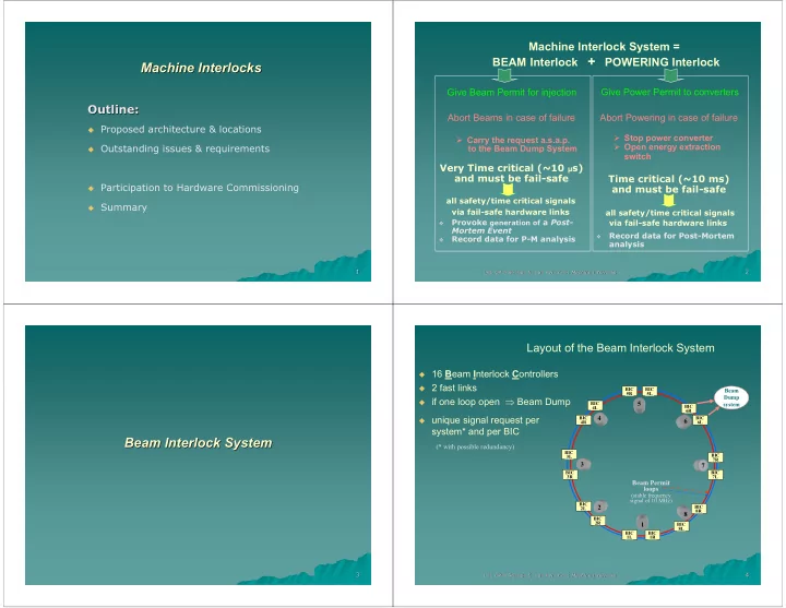
Layout of the Beam Interlock System

(* with possible redundancy) unique signal request per

system* and per BIC

16 Beam Interlock Controllers 2 fast links if one loop open ⇒ Beam Dump

BIC 1R BIC 1L BIC 2R BIC 2L BIC 8L BIC 8R BIC 7L BIC 7R BIC 6R BIC 6L BIC 5R BIC 5L BIC 4L BIC 4R BIC 3L BIC 3R

1 8 7 6 5 4 3 2

Beam Dump system

Beam Permit loops

(stable frequency signal of 10 MHz)

slide-2
SLIDE 2

LHC CP LHC CP-

  • 4 Session 5.3 on Hw

4 Session 5.3 on Hw Com Comg

g:

: Machine interlocks Machine interlocks

5 5

Beam Interlock Controller BIC

Local output

  • Embedded in VME/LynxOS

( for monitoring purpose) Monitor Control Network time stamping

  • Time stamping input for P.M.

Injection BLM (at left) RF Collimators Warm Magnets BLM (at right) Vacuum Access Experiments

Matrix

  • Consists in Hardware “Matrix”

Out

In In

  • Interrupts the Beam Permit loops

from previous BIC Beam Permit loops to next BIC

Powering Interlock Beam Excursion

LHC CP LHC CP-

  • 4 Session 5.3 on Hw

4 Session 5.3 on Hw Com Comg

g:

: Machine interlocks Machine interlocks

6 6

Location of Beam Interlock Controllers

UA 63

1 8 7 6 5 4 3 2

UA 67 UA 83 UA 87 UA 23 UA 27 UA 43 UA 47

USC

55 UJ 56 UJ 76 UJ 76 UJ 33 UJ 33 US 15 US 15

All installed in underground areas Ethernet connection Timing connection Powered by UPS

LHC CP LHC CP-

  • 4 Session 5.3 on Hw

4 Session 5.3 on Hw Com Comg

g:

: Machine interlocks Machine interlocks

7 7

Outstanding issues (1/2)

180 Connections for Dump requests Various electronics

⇒ Interlock Client Box proposed

Interface Client / BIC must be finalized

Beam Interlock Controller Beam Interlock Controller Interlock Interface card

Beam Dump Request

Client Interface ”Boxes”

Beam Dump Request

LHC CP LHC CP-

  • 4 Session 5.3 on Hw

4 Session 5.3 on Hw Com Comg

g:

: Machine interlocks Machine interlocks

8 8

Outstanding issues (2/2)

Timing Control Network

Specialist programs Operator console

3-tier Architecture (JAVA, J2EE + CMW) ) Safety analysis must be performed

Logging

Alarms P.M.

BIC #1 BIC #1 BIC BIC #16 #16 . . . . . . BIC #2 BIC #2

Beam Permit Loops Solution using 3-tier Architecture

proposed for equipment access ⇒ Validation after SPS Extraction Tests?

Interfaces with Logging, Alarms, &

P.M. not yet defined

slide-3
SLIDE 3

LHC CP LHC CP-

  • 4 Session 5.3 on Hw

4 Session 5.3 on Hw Com Comg

g:

: Machine interlocks Machine interlocks

9 9

Injection Tests Injection Tests

Participation with 3 BICs 1 “Beam Permit Loop” Injection system BLM ? Powering Interlock Warm Magnets Vacuum Access Possible clients: If loop open ⇒ Injection veto 8 7

SPS

1

LHC

BIC 8R BIC 7L BIC 8L

10 10

Powering Interlock System Powering Interlock System

LHC CP LHC CP-

  • 4 Session 5.3 on Hw

4 Session 5.3 on Hw Com Comg

g:

: Machine interlocks Machine interlocks

11 11

From Sector to Subsectors…

IP7

Matching Sections

Arc continuous cryostat

Inner Triplet

IP8

Warm magnets . . . . . . . .

1 8 7 4 6 5 4 3 2 Sector 7-8

LHC CP LHC CP-

  • 4 Session 5.3 on Hw

4 Session 5.3 on Hw Com Comg

g:

: Machine interlocks Machine interlocks

12 12

zone including the magnets at room temperature

X.L8 M.L8 A.78

SIEMENS SIEMENS

26 43

SIEMENS

15 P.L.C.

SIEMENS

14

Number of electrical circuits managed by the PIC IT Network

POWERING Subsectors in 7-8

to Beam Interlock

Not to scale Arc continuous cryostat

Inner Triplet Matching Sections

IP7

LHC-B

IP8

slide-4
SLIDE 4

LHC CP LHC CP-

  • 4 Session 5.3 on Hw

4 Session 5.3 on Hw Com Comg

g:

: Machine interlocks Machine interlocks

13 13

M.R8 L.L1

P.L.C.

SIEMENS

14

X.R8 X.L1

SIEMENS

13

SIEMENS

14

SIEMENS SIEMENS

26 43

SIEMENS

15 Atlas

# electrical circuits managed Control Network to Beam Interlock to Beam Interlock

A.81

LHC-b

Matching Section Matching Sections

Arc continuous cryostat

Inner Triplet Inner Triplet

IP8 IP1

POWERING Subsectors in 8-1

LHC CP LHC CP-

  • 4 Session 5.3 on Hw

4 Session 5.3 on Hw Com Comg

g:

: Machine interlocks Machine interlocks

14 14

POWERING Subsectors

M.L2 M.L2 X.R1 X.R1

2 2

X.L2 X.L2 12 12 A A L.R1 L.R1

1 1

X.R2 X.R2

3 3

23 23 A A M.R2 M.R2

2 2

M.L4 M.L4

4 4

34 34 A A

3 3

L.L5 L.L5

5 5

X.L5 X.L5 45 45 A A L.R4 L.R4

4 4

M.L6 M.L6 X.R5 X.R5

6 6

56 56 A A L.R5 L.R5

5 5 7 7

67 67 A A L.R6 L.R6

6 6

M.L8 M.L8

8 8

X.L8 X.L8 78 78 A A

7 7

L.L1 L.L1 X.R8 X.R8

1 1

X.L1 X.L1 81 81 A A L.R8 L.R8

8 8

Functional specification EDMS No361532: ”The Powering Subsectors” LHC CP LHC CP-

  • 4 Session 5.3 on Hw

4 Session 5.3 on Hw Com Comg

g:

: Machine interlocks Machine interlocks

15 15

Powering Interlock Controllers Location

UA23 UA23 UJ16 UJ16 2 2 UA23 UA23 UA23 UA23 RR17 RR17 1 1 UA27 UA27 3 3 UJ33 UJ33 UA27 UA27 UA27 UA27 2 2 UA43 UA43 4 4 UA43 UA43 UJ33 UJ33 3 3 RR53 5 5 USC55 USC55 RR53 UA47 UA47 UA47 UA47 4 4 UA63 UA63 UJ56 UJ56 6 6 UA63 UA63 RR57 RR57 5 5 7 7 RR73 UA67 UA67 UA67 UA67 6 6 UA83 UA83 8 8 UA83 UA83 UA83 UA83 RR77 7 7 RR13 UA87 UA87 1 1 UJ14 UJ14 RR13 UA87 UA87 UA87 UA87 8 8

Technical Services required: Ethernet & UPS

I I P P I I P P

SIEMENS SIEMENS SIEMENS SIEMENS SIEMENS SIEMENS

LHC CP LHC CP-

  • 4 Session 5.3 on Hw

4 Session 5.3 on Hw Com Comg

g:

: Machine interlocks Machine interlocks

16 16

Quench Quench Quench Protection System Quench Protection System

Interlock signals for one electrical circuit

Discharge Request

Discharge Req.

Quench Protection System Power Converter

Permit Failure

SIEMENS

Powering Interlock Controller Abort Quench signal

to Beam Interlock

redundancy redundancy

Engineering specification EDMS No368927: The Interfaces between Powering Interlock System, Power Converters and Quench Protection System

slide-5
SLIDE 5

LHC CP LHC CP-

  • 4 Session 5.3 on Hw

4 Session 5.3 on Hw Com Comg

g:

: Machine interlocks Machine interlocks

17 17

  • ~900 different converters to handle

( 60 Amp. Orbit correctors not considered)

Powering Interlock Classes

  • Managed through Interlock Classes

following the LHC Reference Database

  • Depending of the class the attached

process differs after a quench or a failure:

  • Abort (or not) Powering in the concerning Subsector
  • Request (or not) a Beam Dump
SIEMENS

LHC Reference Database PLC CONFIGURATION: PIC Name Circuit Name Hw Interface Type PAR_BD PAR_PS

LHC CP LHC CP-

  • 4 Session 5.3 on Hw

4 Session 5.3 on Hw Com Comg

g:

: Machine interlocks Machine interlocks

18 18

Outstanding issues & Requirements

(Time Stamping via NTP) Radiation tolerant Hw solution

must be finalized for RR

SIEMENS

PIC #1 PIC #1 PIC #36 PIC #36

SIEMENS

. . . . . .

IT Network IT Network

SIEMENS

PIC #2 PIC #2 Operator console

LHC Reference LHC Reference Data base Data base Static configuration

Logging

Alarms P.M.

“Accurate” Time Stamping via

NTP (~1ms)

QPS

Cryo

?

Safety analysis “A.U.G” Interface UPS Interface Interfaces with Cryo & QPS Interface with Supervision

has to be chosen

Interfaces with Logging,

Alarms, & Post-Mortem not yet defined

UPS UPS UPS . . .

19 19

Warm Magnets Interlock System Warm Magnets Interlock System

LHC CP LHC CP-

  • 4 Session 5.3 on Hw

4 Session 5.3 on Hw Com Comg

g:

: Machine interlocks Machine interlocks

20 20

Patch Panel

8 Separation dipole - MBW 8 Correction dipole - MCBW 20 Twin aperture quadrupole - MQW A 4 Twin aperture quadrupole - MQW B

Tunnel

Patch Panel

UJ76 Surface SR7

Schéma de principe des interlocks des "aimants chauds" au point 7 du LHC

Left side Right side

3 Converters in SR7:

RD34.LR7 RQ4.LR7 RQ5.LR7

12 Converters in UJ76 :

RCBWH4.L7B1 - RCBWH5.L7B2 - RCBWV4.L7B2 RCBWV5.L7B1 - RCBWH4.R7B2 - RCBWH5.R7B1 RCBWV4.R7B1 - RCBWV5.R7B2 - RQT4.L7 RQT5.L7 - RQT4.R7 - RQT5.R7 SR7 NE48 cable NE48 cables Siemens PLC S7-300 + I/O Ethernet

IP7

P.Dahlen AT/MEL

slide-6
SLIDE 6

LHC CP LHC CP-

  • 4 Session 5.3 on Hw

4 Session 5.3 on Hw Com Comg

g:

: Machine interlocks Machine interlocks

21 21

Récapitulatif du nombre d’aimants « Récapitulatif du nombre d’aimants « chauds chauds » » dans lignes de transfert et LHC dans lignes de transfert et LHC

CNGS CNGS-

  • TT41

TT41 TI8 TI8 TI2 TI2 Zone Zone 18 18 108 108 28 28 401 401 33 33 308 308 # # Conv Conv. . # Aimants # Aimants 15 15 44 44 Point 3 Point 3 1 1 12 12 Point 5 Point 5 2 2 30 30 Point 6 Point 6 15 15 40 40 Point 7 Point 7 Point 8 Point 8 Point 2 Point 2 Point 1 Point 1 3 3 3 3 3 3 3 3 1 1 12 12

P.Dahlen AT/MEL

LHC CP LHC CP-

  • 4 Session 5.3 on Hw

4 Session 5.3 on Hw Com Comg

g:

: Machine interlocks Machine interlocks

22 22

Outstanding issues for Warm Magnets Interlock

SIEMENS

WPIC #1 WPIC #1 WPIC #n WPIC #n

SIEMENS

. . . . . .

IT Network IT Network

SIEMENS

WPIC #2 WPIC #2 Operator console Logging

Alarms P.M. ?

Interface with Supervision

has to be chosen

Interfaces with Logging,

Alarms, & Post-Mortem not yet defined

LHC CP LHC CP-

  • 4 Session 5.3 on Hw

4 Session 5.3 on Hw Com Comg

g:

: Machine interlocks Machine interlocks

23 23

Machine Interlocks Systems Machine Interlocks Systems & & Hardware Commissioning Hardware Commissioning

LHC CP LHC CP-

  • 4 Session 5.3 on Hw

4 Session 5.3 on Hw Com Comg

g:

: Machine interlocks Machine interlocks

24 24

Hardware Commissioning

"PIC test system" for Q4/03 Tests procedures “ similar as ” the String2 one Commissioning dates according HCWG schedule Dedicated Beam Interlock commissioning could be partially done. Two phases:

– 2) Before injecting beams: mandatory test of the whole system with all Interlock clients and the closed Beam Permit Loops.

Strategy discussed into MPWG ⇒ Sketch proposed to HCWG

– 1) Single test for client/BIC interface

Beam Interlock: Powering Interlock: Warm Magnets Interlock:

Procedure & dates must be discussed in the HCWG…

slide-7
SLIDE 7

LHC CP LHC CP-

  • 4 Session 5.3 on Hw

4 Session 5.3 on Hw Com Comg

g:

: Machine interlocks Machine interlocks

25 25

Conclusions Conclusions

Started late but … Thanks to… Outstanding issues rely on AB/CO competence and skills… Confidence… Participation to the Hw Com. according to HCWC procedures

and proposals

Questions?…