analysis and non destructive evaluation of composite
play

ANALYSIS AND NON-DESTRUCTIVE EVALUATION OF COMPOSITE OVERWRAPPED - PDF document

18 TH INTERNATIONAL CONFERENCE ON COMPOSITE MATERIALS ANALYSIS AND NON-DESTRUCTIVE EVALUATION OF COMPOSITE OVERWRAPPED THICK-WALLED CYLINDERS S. T. Ahn 1 *, K. J. Kang 1 , C. K. Cho 1 1 Agency for Defense Development, Daejeon, Republic of Korea *


  1. 18 TH INTERNATIONAL CONFERENCE ON COMPOSITE MATERIALS ANALYSIS AND NON-DESTRUCTIVE EVALUATION OF COMPOSITE OVERWRAPPED THICK-WALLED CYLINDERS S. T. Ahn 1 *, K. J. Kang 1 , C. K. Cho 1 1 Agency for Defense Development, Daejeon, Republic of Korea * Corresponding author(congzi@add.re.kr) Keywords : thick-walled cylinder, composite, tape placement, non-destructive evaluation Multilayer tubes were introduced around 1870.[2] 1 Introduction Here, the wall of the tube is composed of several Since gun powder was discovered, guns have been layers, where, in one method, tube rings, or jackets, changed and developed in terms of their overall or both are shrunk onto the liner. In another design, configuration and firing mechanism with their many layers of steel bands or composite plies are performance over a period of several centuries. The wound onto the liner with tensile stress. In either most principal requirements have been mobility and case, the tensile stresses arising in the exterior layers, firepower. However, these two characteristics are because of the shrink fitting or winding, result in never compatible. Weapon systems must be light for compressive stresses on the interior layers of the high mobility, but wall-thickness of gun tube should tube. The Compressive stresses present in the be thick enough to resist required firepower. interior region of the wall of the tube, even in the In the viewpoint of operation, light weight for unloaded state, compensate to a great extent the mobility is a key factor as well as firepower. SAFE loading during firing, while the tensile stresses in the is the abbreviation of operational procedure of exterior portion of the tube wall are insignificantly weapon systems; see, aim, fire and eliminate.[1] increased by the loading. In this way the stress is Adequate firepower is required to eliminate targets distributed over the entire tube cross section, so that effectively. However, weight reduction of weapon the material is well utilized. The stresses in a systems helps obtain better performance on the steps multilayer tube are pictured in Fig.1(b) in the state of ‘aim’ and ‘fire’ out of the four steps. of rest and when firing. Steel, iron or bronze were normally used for monobloc tubes until the middle of the nineteenth century. The use of the barrels as monobloc tubes is 
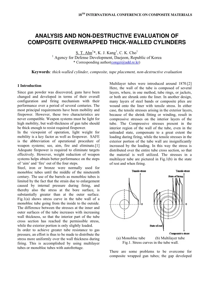
limited by the fact that the strain due to enlargement caused by internal pressure during firing, and thereby also the stress at the bore surface, is substantially greater than at the outer surface. Fig.1(a) shows stress curve in the tube wall of a monobloc tube going from the inside to the outside. The difference between the stresses at the inner and outer surfaces of the tube increases with increasing wall thickness, so that the interior part of the tube cross section has reached the permissible stress, while the exterior portion is only slightly loaded. In order to achieve greater tube resistance to gas pressure, an effort is thus to be made to distribute the (a) Monobloc tube (b) Multilayer tube stress more uniformly over the wall thickness during Fig.1. Stress curves in the tube wall. firing. This is accomplished by using multilayer tubes or monobloc tubes with autofrettage. There are some problems to be overcome for composite wrapped gun tubes; the gap developed

  2. between steel and composite due to the coefficient the ends and therefore the stresses and strains are of thermal expansion (CTE) mismatch of the two independent of the axial coordinate x. materials, lack of pre-stress on the composite, poor manufacturability for mass production, and so on.[3] The gap issue could be solved by autofrettage after winding process. This process also helps achieve residual stress. However, the thermal soak treatment process cannot be carried out after autofrettage which is essential and bore surface of gun tubes cannot be chrome-plated that is generally required in these days.[4] Another way to solve these problems could be the lay-up tailoring. Using both fiberglass and graphite together with the ply angles being adjusted such that the lay-up’s CTE matched that of the steel avoids forming the gap. However, it can degrade the Fig.2. Definition of the coordinate axes. performance of the composite.[5] In this study, IM7/PEEK tape is consolidated onto a The composite overwrapped thick-walled cylinder steel thick-walled cylinder, in situ, using the robotic can be described as an n-layer cylinder, which the equipment for tape placement and this equipment steel mandrel being referred to as the first layer. The can apply the requested tension during winding. This outer radius of the cylinder is r o and the inner radius process is expected to decrease the thermal is r i . The interface between the k th layer and the expansion effect and prevent the gap formed (k+1) th layer is denoted as r k+1 . The inner pressure between the steel and the composite effectively. and the outer pressure are P i and P o respectively. The Since this process can be done after both cylinder is subjected to a torsion load τ o and an axial autofrettage and chrome-plating processes, it is force F axial . Each layer may also be subjected to a suitable for the gun barrel application. In addition, thermal loading Δ T (k) , where the superscript (k) the post cure cycle for thermoplastic composite is denotes the k th layer. not necessary due to the ‘cure in place’ method with In the x- θ -r coordinate system, the constitutive the thermoplastic composite. behavior of each layer is expressed as: ( ) k ⎛ ⎞ 0 0 ( ) C C C C ( ) ⎛ σ ⎞ k ⎛ ε − α Δ ⎞ k 11 12 13 16 T ⎜ ⎟ x x x ⎜ ⎟ ⎜ ⎟ 2 Composite overwrapped thick-walled cylinders ⎜ ⎟ σ 0 0 ε − α Δ (1) C C C C T ⎜ ⎟ 12 22 23 26 ⎜ ⎟ θ θ θ ⎜ ⎟ ⎜ ⎟ ⎜ ⎟ σ ε − α Δ 0 0 ⎜ C C C C ⎟ T 2.1 Plane strain cylinder theory 13 23 33 36 = ⎜ r ⎟ ⎜ x x ⎟ ⎜ ⎟ τ γ ⎜ ⎟ 0 0 0 0 ⎜ ⎟ C C θ ⎜ 44 45 ⎟ θ The generalized plane deformation analysis r r ⎜ ⎟ ⎜ ⎟ τ γ ⎜ ⎟ 0 0 0 0 ⎜ ⎟ C C ⎜ ⎟ presented by Hyer [6] is the basis of this work. xr xr 45 55 ⎜ ⎟ ⎜ ⎟ ⎜ ⎟ τ γ − α Δ ⎜ ⎟ ⎝ ⎠ ⎝ T ⎠ θ 0 0 θ θ ⎝ ⎠ However, instead of formulating a problem in terms x C C C C x x 16 26 36 66 of a scaling variable ζ , such that ζ = Ω r. This scaling is done to avoid numerical problems, which is α The C terms are the elastic constants and the ij j explained later. terms are the coefficients of thermal expansion of It is desired to determine the response of a laminated the k th layer in the global x- θ -r system, which are cylinder subjected to both mechanical and thermal obtained by rotating the lamina properties in the loading. The geometry is defined in the cylindrical principle 1-2-3 material system by the winding angle x- θ -r coordinate system as shown in Fig.2. Since Φ as shown in Fig.2. The problem is formulated in only axi-symmetric loading is considered, the terms of scaled variable ζ as mentioned earlier. displacements, stresses and strains are independent Based on the axi-symmetric and plane deformation of the circumferential coordinate θ . Attention is assumptions, the components of strain for each layer focused on the response of the cylinder away from can be expressed in terms of the axial displacement

Download Presentation
Download Policy: The content available on the website is offered to you 'AS IS' for your personal information and use only. It cannot be commercialized, licensed, or distributed on other websites without prior consent from the author. To download a presentation, simply click this link. If you encounter any difficulties during the download process, it's possible that the publisher has removed the file from their server.

Recommend


More recommend