
SLIDE 1
4-1.1
2/15/06
DURA-SLIDE
FOR MORE INFORMATION CALL US AT 1-800-588-0174 OR 860-589-6364 FAX: 860-589-6235 VISIT US AT www.RIMFG.com
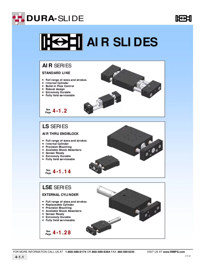
AI R SLI DES
AI R SERIES 4 - 4 -1 . 1 .2 2
STANDARD LI NE
- Full range of sizes and strokes
- I nternal Cylinder
- Build-in Flow Control
- Robust design
- Extremely Durable
- Fully field serviceable
See Page
LS SERIES 4 - 4 -1 . 1 .1 4 1 4
AI R THRU ENDBLOCK
- Full range of sizes and strokes
- I nternal Cylinder
- Precision Mounting
- Available Shock Absorbers
- Sensor Ready
- Extremely Durable
- Fully field serviceable
See Page
LSE SERIES 4 - 4 -1 . 1 .2 8 2 8
EXTERNAL CYLI NDER
- Full range of sizes and strokes
- Replaceable Cylinder
- Precision Mounting
- Available Shock Absorbers
- Sensor Ready
- Extremely Durable
- Fully field serviceable
See Page